and Temperature Compensation
By Kevin Custer - W3KKC
Captions by Robert W. Meister - WA1MIK

|
MASTR II ICOM Rebuild and Temperature Compensation By Kevin Custer - W3KKC Captions by Robert W. Meister - WA1MIK |
|
Concept:
The concept of this article is to help you prepare a GE MASTR II ICOM for crystal replacement
and temperature compensation using the
CH-25 Crystal Heater from Kevin Custer. The photos
here will help you through the process of getting the ICOM ready for crystal replacement and
adding the heater resistors and temperature sensor, while allowing the original metal cover
to be reinstalled. A slot is cut into the side of the ICOM's metal case to allow the wires to
protrude out from the inside. A standard EC ICOM is all that is necessary, as you won't need the
original temp-comp IC installed in the 2C or 5C ICOM. This doesn't mean you can't use a 5C or 2C
with this accessory, it simply means you don't need to start out with one to obtain the
specified temperature stability. In fact, if you have a 2C or 5C, you'll remove the temperature
compensation IC and replace it with two resistors as shown below.
See the following photos for a step-by-step preparation of the ICOM.
Clicking on any photo may make the image larger. Clicking it again may enlarge it even
more. Use your browser's "Back" button to return to the article.
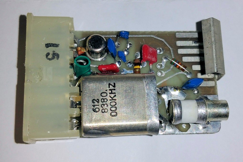
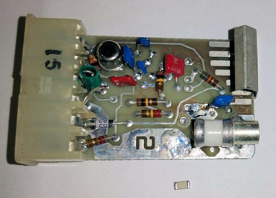
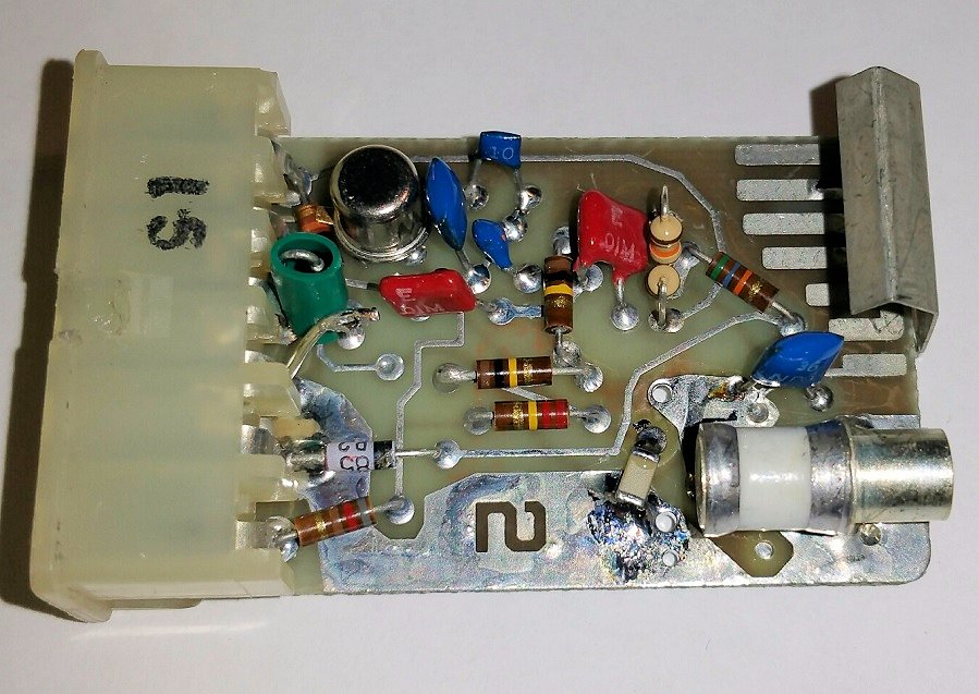
Here's the inside of the stock ICOM.
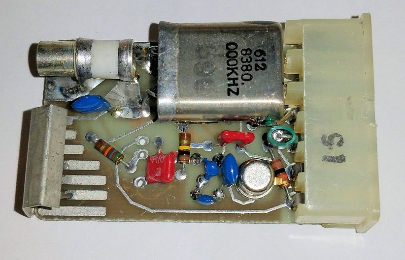
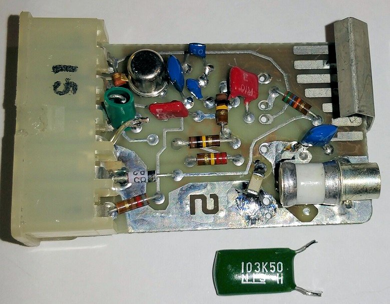
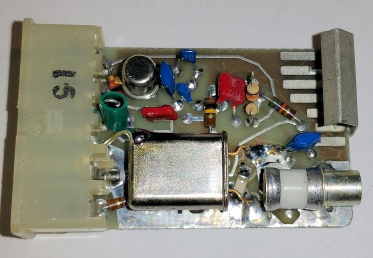
And another view.
As you can see, the thickness of the module is just enough to accomodate the crystal
and the green 0.01uF capacitor underneath it.

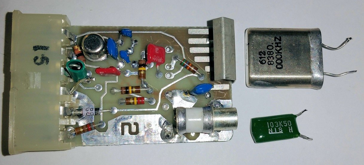
After removing the original crystal, you can see the components that are present
underneath it.
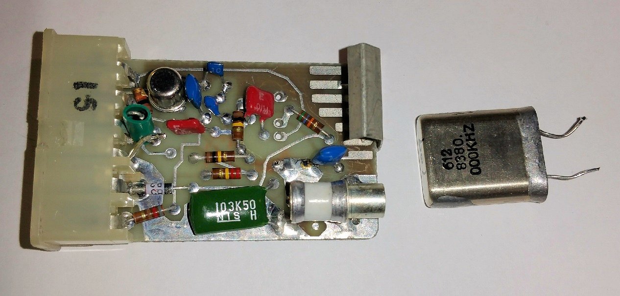
Here, that green capacitor has been removed as well.
A 0.01uF chip capacitor is sitting below the ICOM, ready to be be soldered to the
circuit board in place of that green capacitor.
Here, the chip capacitor has been soldered to the pads where the green capacitor was.
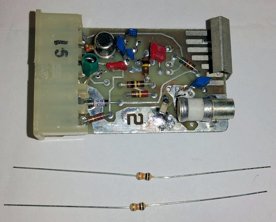
This EC ICOM had no temperature-compensation module in it, and the radio it will be installed
in doesn't have any temp-comp ICOM or module either. To properly bias the temp-comp voltage, a
pair of 10k 1/8w resistors are wired in series and will be installed in this ICOM.
Here the resistor leads have been twisted together in preparation for installation. All
three leads are required.
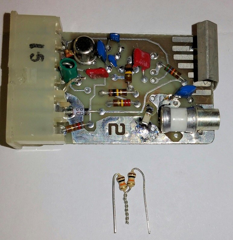
The two resistors are inserted into the three empty holes in the upper right section of
the ICOM. This is where the internal temp-comp module would have normally been installed if it
were a 5C or 2C. In this case, there was no temp-comp module because the ICOM is a EC.
If your ICOM has a temp-comp IC in it, remove it and clean out the holes for installation of
the two 10k bias resistors.
The NEW crystal may now be installed into the module.
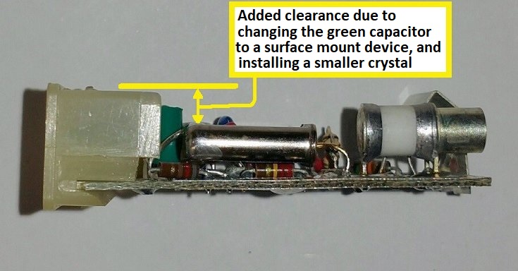
By removing that green capacitor under the crystal, there is now sufficient space
available above the crystal to accomodate the heater resistors and temperature sensor.
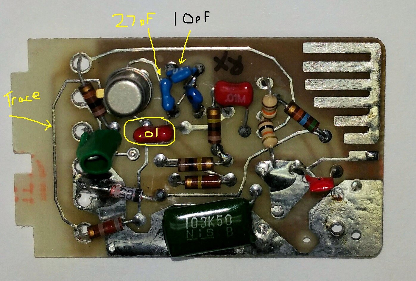
This photo shows the hidden trace under the module's nylon connector at the left side.
It also identifies the value of two small capacitors in the oscillator section.
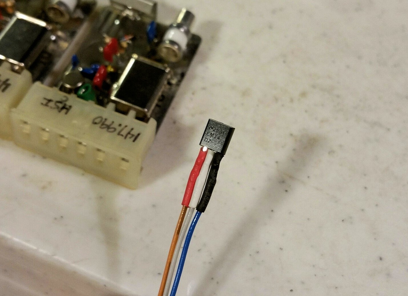
The LM34 temperature sensor is prepared with wires and heat shrink tubing over the
individual leads.
Here's a stock ICOM ready to have the heater resistors and temperature sensor
epoxied to the crystal.
The heater resistors and temperature sensor have been epoxied to the outside of the
crystal. The leads are positioned to fit through a slot that will be cut in the side of
the ICOM's metal case.
Here, a slot has been cut in the side of the case to accomodate the wires that must
pass out of the ICOM. Note the rolled end to prevent wire chafing.
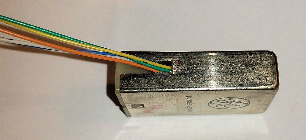
Here's a photo of the closed ICOM with the crystal heater wires coming out of the
slot on the side. This ICOM is ready to be installed in the radio and attached to the
crystal heater circuit board.
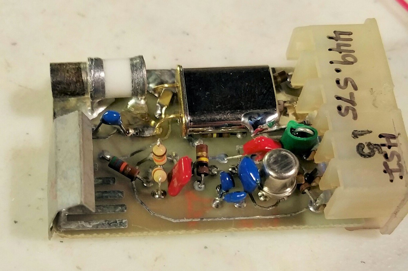
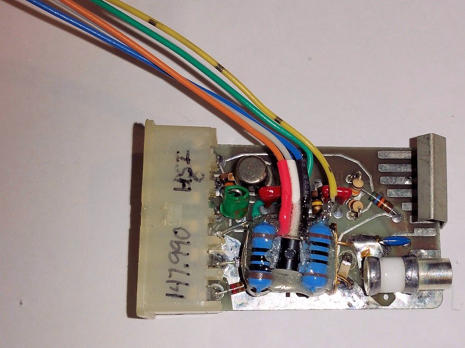
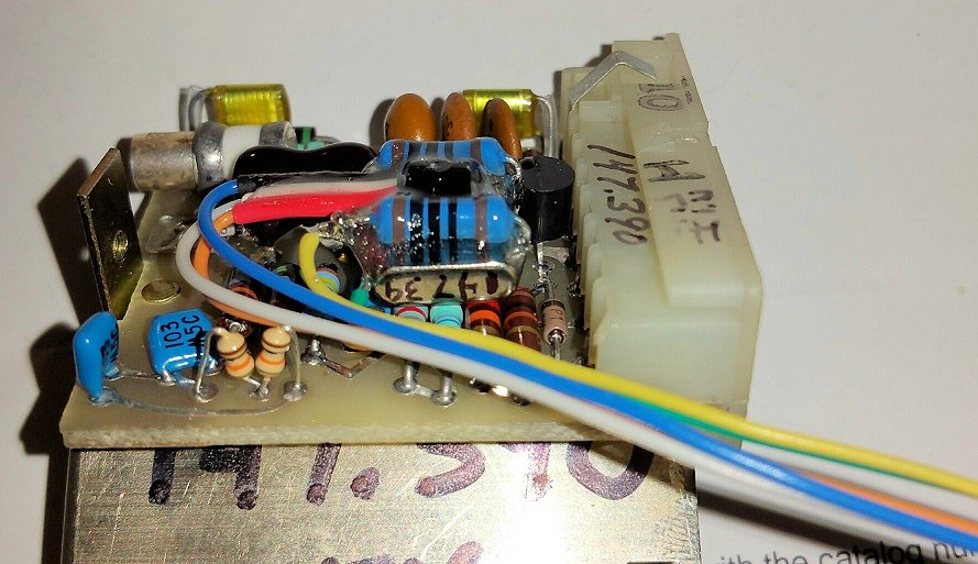
The FM ICOM is a bit larger and is laid out differently, but it needs the same
two 10k resistors (seen along the edge closest to the viewer) and the heater resistors
and temperature sensor glued to the crystal.
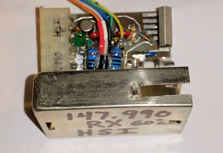
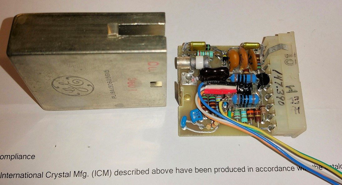
Here's a photo of the completed FM ICOM ready to have its cover reinstalled. Note
the notch for the wires to pass through and rolled edge.
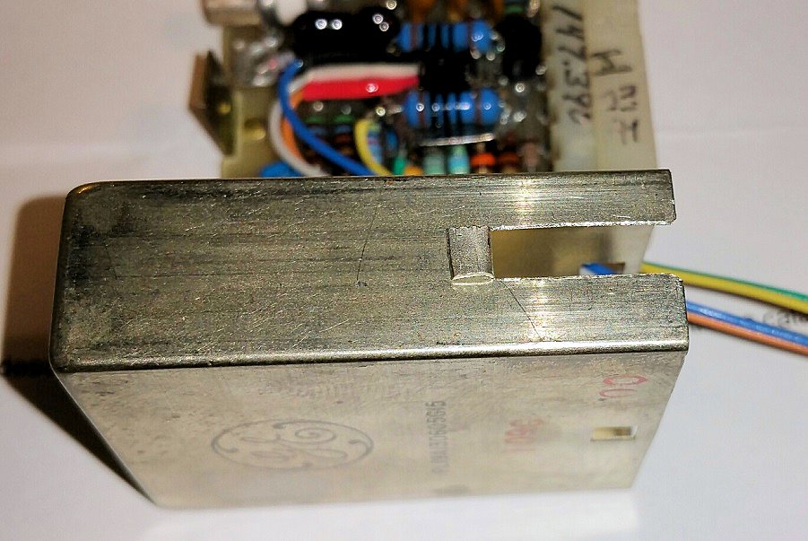
A close-up of the notch cut into the cover. Note the position of the notch relative
to the top and bottom of the cover.
Contact:
You can contact the author at kuggie@kuggie.com
This page originally posted on April 15, 2015
Article photos © Copyright 2015 Kevin K. Custer - W3KKC.
Photo captions © Copyright 2015 Robert W. Meister - WA1MIK.
Artistic layout and hand-coded HTML © Copyright 2015 and date of
last update by Kevin Custer.
This web page, this web site, the information presented in and on its pages and in these modifications and conversions is © Copyrighted 1995 and (date of last update) by Kevin Custer W3KKC and multiple originating authors. All Rights Reserved, including that of paper and web publication elsewhere.