Masters Communications
5 Pole Audio Filters
PLF-15 High-Pass
and FL-10 Low-Pass
By Robert W. Meister WA1MIK

|
Evaluation of the Masters Communications 5 Pole Audio Filters PLF-15 High-Pass and FL-10 Low-Pass By Robert W. Meister WA1MIK |
|
Background:
Kevin sent me three filter kits - one high-pass, two low-pass - to construct and evaluate. After they arrived I verified the components with the parts list and familiarized myself with their placement. I kept the three kits separate so I wouldn't mix up the parts. Each filter has about 18 parts and assembly is very simple and straightforward. Per Kevin's request, I did not install the 4-pin headers; those are only required if the FL-10 is to be used with Masters Communications Radio Adapters (RA or DRA) that have the mating receptacle to use the FL-10. The circuit boards are VERY small: about 0.9 by 1.35 inches (or 23 by 34 millimeters). Here's a photo showing both sides of the boards. Click on any photo or graph for a larger view.
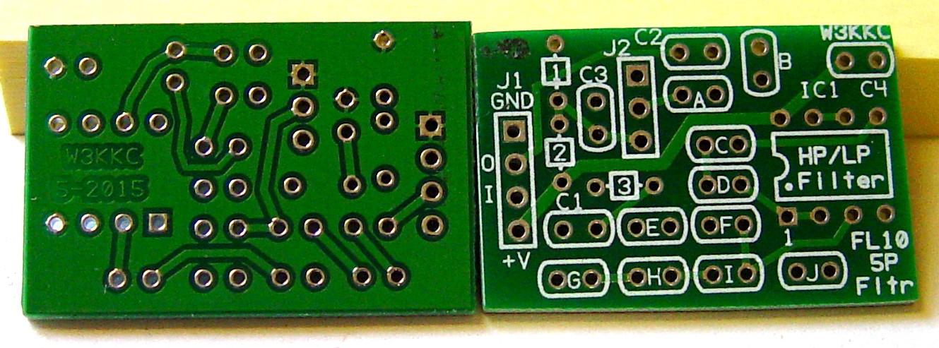
NOTE: While this evaluation was done with the FL-10 product, the PLF-15 CTCSS filter has the same form factor, components, specifications, and performance as the FL-10.
Design:
The FL-10 consists of two Sallen-Key filter stages and a bias voltage supply. The first stage (U1A) is a 3-pole filter that provides an attenuation of 18dB per octave. The second stage (U1B) is a 2-pole filter that provides an attenuation of 12dB per octave. Together these form a 5-pole filter capable of an attenuation of 30dB per octave in the cutoff frequency range and no attenuation in the pass-band frequency range. The Low-Pass Filters are designed to pass all frequencies up to about 4 kHz or 15 kHz then start attenuating the signal. The FL-10 was initially designed as a Low-Pass Filter, however by swapping resistor and capacitor placement and values the FL-10 becomes a High-Pass Filter that attenuates all signals below about 350 Hz. In this high-pass configuration, the product is called the PLF-15 CTCSS Reject filter.
The cut-off frequency is defined as the frequency where the output level is 3dB lower than the input level. For the PLF-15, that occurs at 350 Hz for the High-Pass Filter and for the FL-10, 4 kHz or 15 kHz for these Low-Pass Filters.
The bias voltage supply uses R1 and R2 to create a voltage that's half of the supply voltage. C3 keeps audio signals from modulating the bias supply; additional capacitance is required for proper performance of the High-Pass Filter below 200 Hz.
Parts:
The following is a combined parts list. The FL-10 and PLF-15 web pages have more detailed lists that should be used during construction. All resistors are 1/8 watt 5% unless otherwise noted. See the Component Notes after this table.
| Part | 15 kHz LPF | 4 kHz LPF | 350 Hz HPF / CTCSS |
|---|---|---|---|
| C1 | 1uF (105) | 1uF (105) | Jumper [1] |
| C2 | 1uF (105) | 1uF (105) | 1uF (105) |
| C3 | 1uF (105) | 1uF (105) | 220uF electrolytic [2] |
| C4 | 1uF (105) | 1uF (105) | 1uF (105) |
| J2 | Jumper to Ground [3] | Jumper to Ground [3] | See text; part of C3 |
| R1 | 10k | 10k | 1k 1/4w 5% |
| R2 | 10k | 10k | 1k 1/4w 5% |
| R3 | 100k | 100k | Omitted - do not install |
| A | 0.001uF (102) | 470pF (471) | 8.2k |
| B | 0.01uF (103) | 0.001uF (102) | 2.2k |
| C | 3.3k | 36k | 0.1uF (104) |
| D | 3.3k | 56k | 0.1uF (104) |
| E | 0.0082uF (822) [4] | 0.0033uF (332) | 5.6k |
| F | 0.0022uF (222) | 220pF (221) | 39k |
| G | 1.5k | 10k | 0.068uF (683 or 0.068) |
| H | 3.3k | 100k | 0.068uF (683 or 0.068) |
| I | 1.5k | 30k | 0.068uF (683 or 0.068) |
| J | 0.01uF (103) | 0.0015uF (152) | 2.2k |
Component Notes:
[1]: Use a resistor lead clipping for C1 in the High-Pass Filter.
[2]: Observe the polarity of the electrolytic capacitor C3 in the High-Pass
Filter and install per the text below.
[3]: Use a resistor lead clipping and jumper the Center hole to the Square
(outer) hole (Ground) in the Low-Pass Filter.
[4]: The 8 looks like ||.
Other parts supplied with each filter kit:
When using the FL-10 Low-Pass Filter with a RA-Series radio adapter:
Assembly:
Armed with the parts list, I assembled each filter separately to avoid confusion, starting with the lowest parts first: the wire jumper(s), the resistors, the capacitors, the IC socket, and finally the electrolytic capacitor for the HPF. Even though "the product is all thru-hole to allow assembly and repair by the common technician" the parts are still very small.
I measured every resistor with an ohmmeter prior to installation. I installed all of the resistors vertically, with one end against the circuit board and the other end high, because in some locations they are wider than the holes allocated for them. R1, R2, and R3 do fit flat against the board if you bend the leads close to the body of the part. I built the kits without the benefit of a "finished" photo.
Some capacitor values were very hard to read; I needed a magnifying lens and bright light to see the numbers. I ended up installing the caps whose values I could verify first, leaving the ones I was unsure of for last (by process of elimination). All of the caps except C3 on the HPF are multi-layer ceramic or metallized polyester and are non-polarized, so they can be installed without worrying about polarity.
NOTE: On the PLF-15 HPF, C3 is installed making sure you place the positive lead into the square hole and the negative lead into the round hole. The capacitor has a band that clearly marks the negative (minus) lead. The board has a + sign to show the orientation of the positive lead.
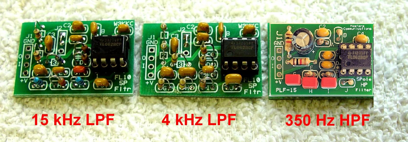
After cleaning the boards, I measured the resistance across the power pins; it read 20k Ohms for each LPF and 2k Ohms for the HPF, the values of R1 and R2 in series. I also made sure power and ground made it to the IC socket at pins 8 and 4 respectively. All units checked out fine and the ICs were finally installed. It took me two hours to assemble, clean, and resistance-check the three filters, but I was going real slow and did just a few components at a time, triple-checking my work as I progressed. Here's a photo of all of the assembled and tested filters.
Performance Measurements:
For each filter, I measured the audio distortion and maximum output level at both 5V and 12V supply voltages. The frequency response was measured with 12V only, as it is not dependent on the supply voltage. The results are shown in the graphs below. Current draw at 12VDC was under 1mA for each LPF and under 7mA for the HPF, increasing slightly when passing audio. The difference is due to the lower values of R1 and R2 used in the HPF.
The input impedance of the filters changes as the frequency changes. I had to monitor and adjust the input signal to maintain the same level at all frequencies. This effect is due to the filter design and should have no effect to the end user, as the change was a maximum of 2dB.
The frequency response was tested with an input level of 2.44Vrms, or +10dBm, which was well below the maximum, using a 12V power supply. The output level was exactly the same as the input level (i.e. unity gain) in the middle of each pass-band. The distortion at this level was around 0.03%.
The signal was considered unacceptable when it reached 1% distortion. With a 5V power supply, this occurred at about 0.6Vrms or 1.7Vp-p and the maximum output level was 0.9Vrms or 2.7Vp-p, but there was almost 5% distortion at that level. Clipping occurred first on the negative peaks of the output waveform. With a 12V power supply, 1% distortion occurred at about 3.3Vrms or 9.6Vp-p and this was also the maximum output level. Clipping was symmetrical with higher input levels.
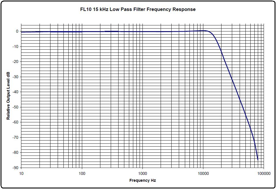
The 15 kHz LPF should pass everything up to approximately 15 kHz, while attenuating signals above that. A 5-pole filter should attenuate at 30dB per octave and this filter exceeds that. Here's its frequency response graph.
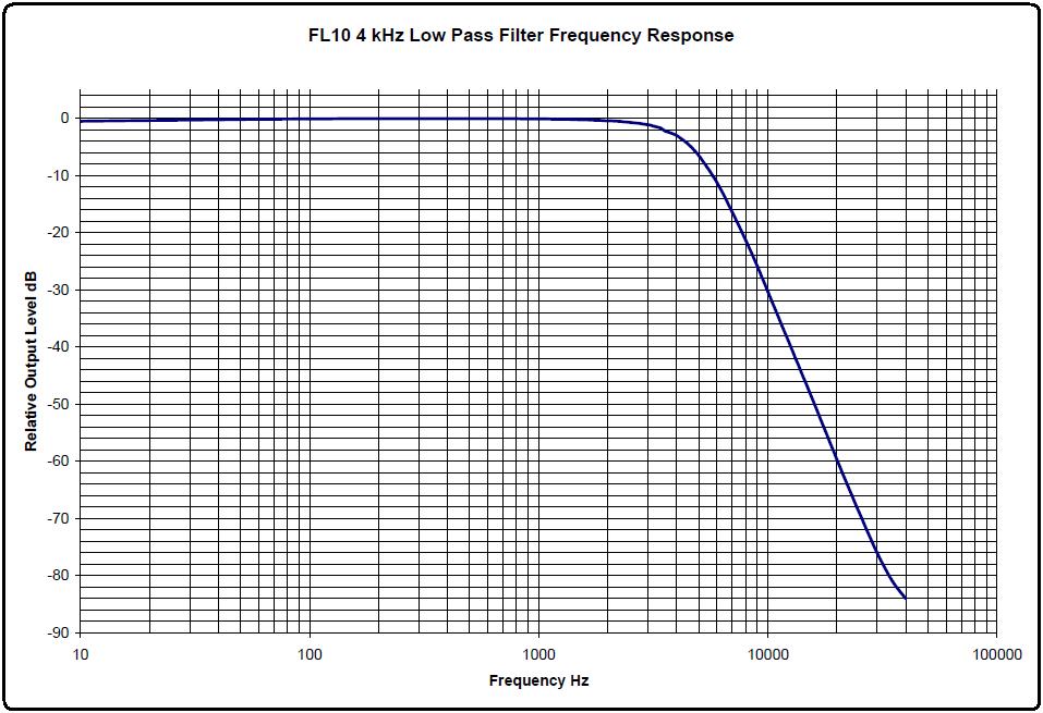
The 4 kHz LPF should pass everything up to approximately 4 kHz, while attenuating signals above that. A 5-pole filter should attenuate at 30dB per octave and this filter exceeds that. Here's its frequency response graph.
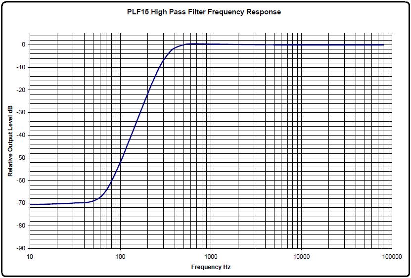
The 350 Hz HPF should pass everything above approximately 350 Hz, while attenuating signals below that. A 5-pole filter should attenuate at 30dB per octave and this filter just makes that. Here's its frequency response graph.
Test Equipment:
HP 339A Distortion Analyzer
Fluke 189 Digital Multimeter
Contact Information:
The author passed away in June 2021. He is greatly missed - W3KKC
This page originally posted on Wednesday 22-Feb-2017
Article text, artistic layout, all photographs, and hand-coded HTML © Copyright 2017 by Robert W. Meister WA1MIK.
This web page, this web site, the information presented in and on its pages and in these modifications and conversions is © Copyrighted 1995 and (date of last update) by Kevin Custer W3KKC and multiple originating authors. All Rights Reserved, including that of paper and web publication elsewhere.