Custom Products from Masters Communications

|
Custom Products from Masters Communications |
|
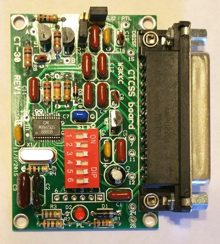
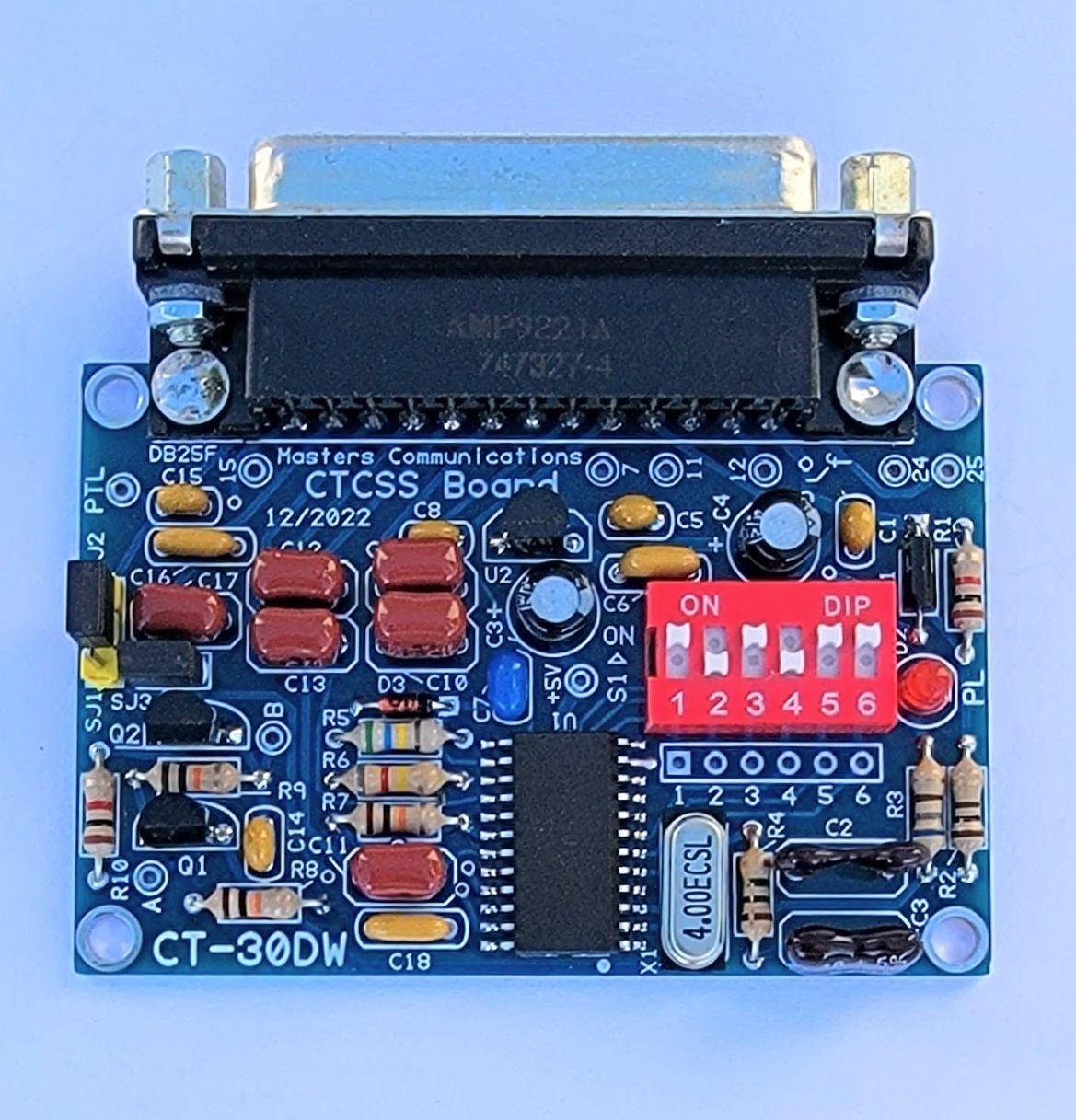
Large top photo of the CT-30 and CT-30DW PC boards.
Click either one for a larger view.
Assembly:
If you purchased our kit, refer to the parts list and make sure you have all of the components
you need to build the kit.
Click here
for Parts List.
Assembly can be done by personal choice, but you may find it easier to install the shorter components first, followed by the taller ones. Kits are supplied with the MX465 presoldered, and cleaned free of any flux residue.
Install all resistors. Some resistors with the color yellow look orange. If in doubt, use an ohm meter to verify the value before soldering it in place.
Install the diodes and capacitors, observing polarity on all diodes and the polarized capacitors! The square pads are the banded end of the diodes and the + of the electrolytic capacitors. Small capacitors are identified as follows: "474 = .47 uF, "104" = 0.1uF, in other words the first two digits are the value and the third digit is the number of zeroes you add to determine the value.
Then install the transistors (flat to flat on silkscreen). Install the 6-position DIP switch. See photo for DIP switch package orientation. The word "ON" goes towards the DB25 connector.
Install the voltage regulator IC and crystal. Then install the LED (short lead to the square hole) and the three pin and two pin headers, followed by the DB25F.
Information on the MX/FX465.
Click here
to download a manual for the MX/FX465-D5 (DS)
Information on the MX465DW.
Click here
to download a manual for the MX465DW
Email
Kevin Custer for support.
Product of Kevin Custer - W3KKC, all rights reserved.
Specifications may change without notice.
Images property of Kevin Custer - W3KKC
Board layout by Chuck Kelsey.
HTML December 7, 2015, W3KKC All Rights Reserved!