Custom Products from Masters Communications

|
Custom Products from Masters Communications |
|
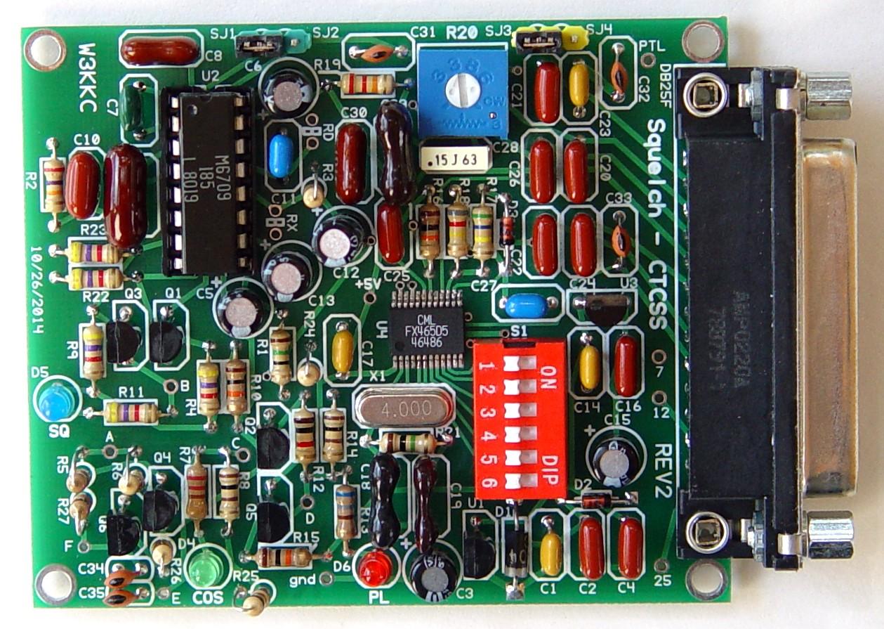
Top photo of the Original SC-50 PC board (click for a larger view).
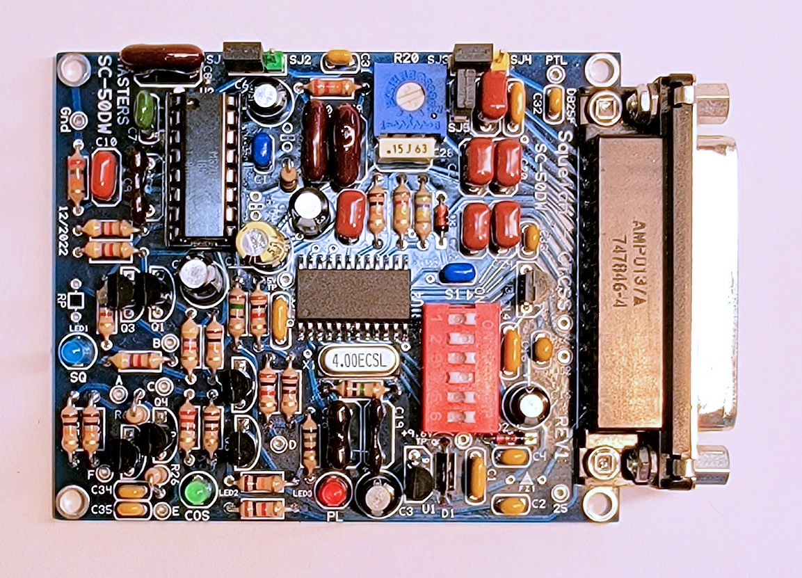
Top photo of the SC-50DW PC board (click for a larger view).
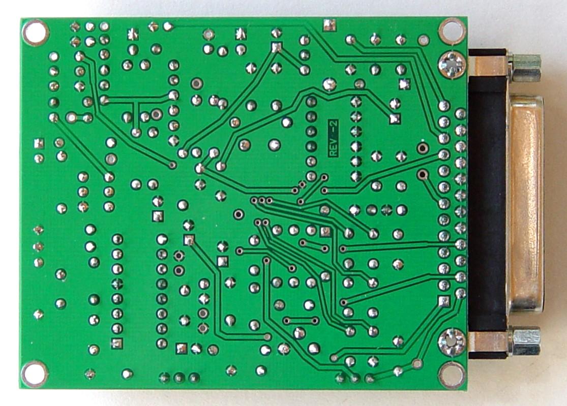
Bottom photo of the Original SC-50 PC board (click for a larger view).
Assembly:
If you purchased our kit, refer to the parts list and make sure you have all of the components
you need to build the kit.
NOTE: The parts list is different between the original and the DW board.
Click here for the Original SC-50 Parts List
Click here for the SC-50DW Parts List
Assembly can be done by personal choice, but you may find it easier to install the surface-mount FX-465 first and do some ohm meter checks to make sure the leads aren't shorted. Pin 1 connects to C17. There is a dimple in the surface-mount package that indicates pin 1. Clean the board of flux. If you bought the kit with the FX-465 already soldered, the board was tested with an ohm meter, and shipped cleaned free of any flux residue.
Install all resistors. There are a few resistors that are easily transposed. Make sure you don't mix up R1 and R21. R1 is a 15 ohm (brown-green-black) while R21 (just under the crystal) is a 1M ohm (brown-black-green). Some resistors with the color violet look dark blue. The 27k (R2) is one of them. If in doubt, use an ohm meter to verify the value before soldering it in place.
Install the diodes and capacitors, observing polarity on all diodes and the polarized capacitors! The square pads are the banded end of the diodes and the + of the electrolytic capacitors. Small capacitors are identified as follows: "101" = 100pF, "102" = 1000pF or 0.001uF, "103" = 0.01uF, "104" = 0.1uF, in other words the first two digits are the value and the third digit is the number of zeroes you add to determine the value.
Then install the transistors (flat to flat on silkscreen). Install the IC socket, and 6-position DIP switch. See photo for DIP switch package orientation. The word "ON" goes towards the DB25 connector.
Install the voltage regulator ICs and crystal. Then install the LEDs (short lead to the square hole) and the three pin headers, followed by the DB25F.
Third Party Compatible Projects:
MABEL is an interface and software that
allows analog control of the Yaesu DR-1X repeater and access to the AllStar VOIP network
with the Raspberry Pi3 and AllStar Asterisk. (Offsite Link)
Information on the FX465.
Click here
to download a manual for the FX465-D5
Email
Kevin Custer for support.
Product of Kevin Custer - W3KKC, all rights reserved.
Specifications may change without notice.
Images property of Kevin Custer - W3KKC Taken by Robert Meister - WA1MIK
Board layout by Chuck Kelsey.
HTML March 7, 2015, W3KKC All Rights Reserved!