Custom Products for the Analog & Digital Radio Amateur Enthusiast

|
Custom Products for the Analog & Digital Radio Amateur Enthusiast |
|
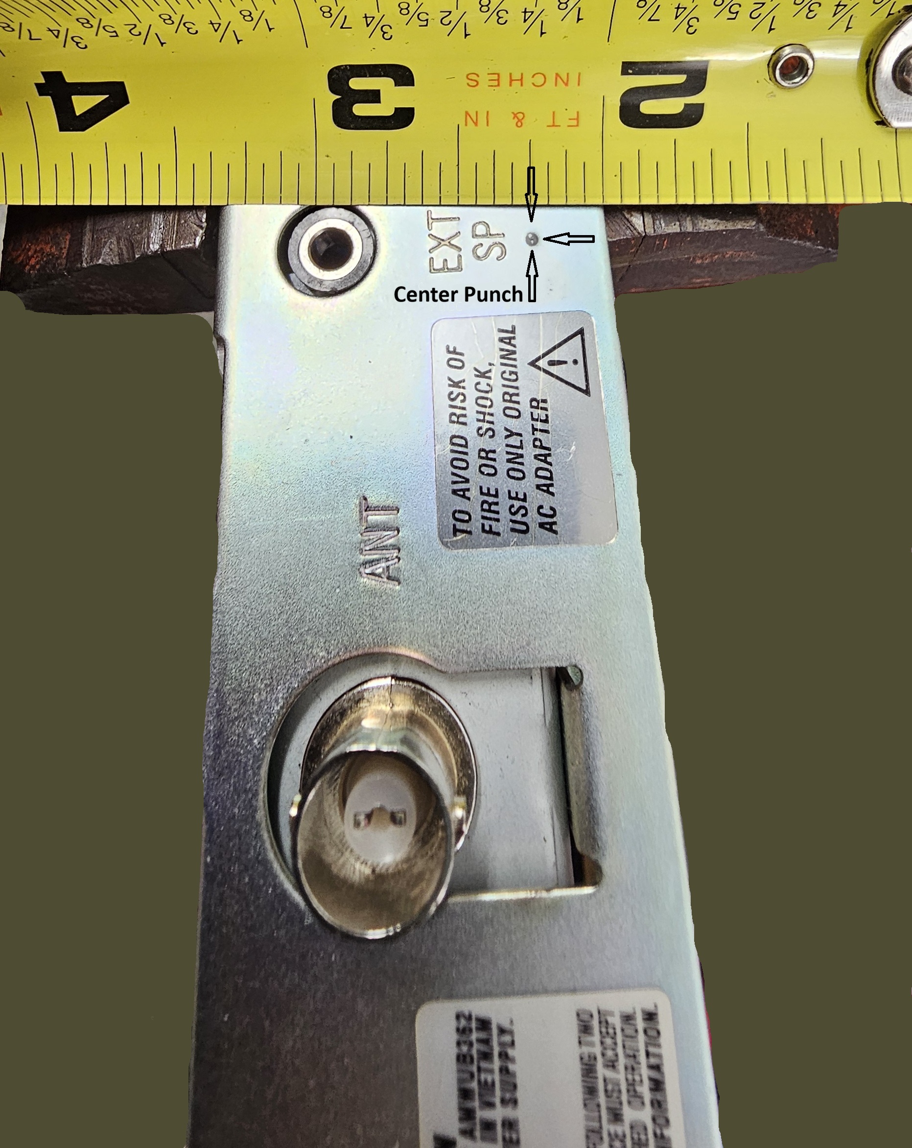
Rear Panel of Bearcat BC355N - center punch - shown enlarged.
(Click photo to show a larger image)
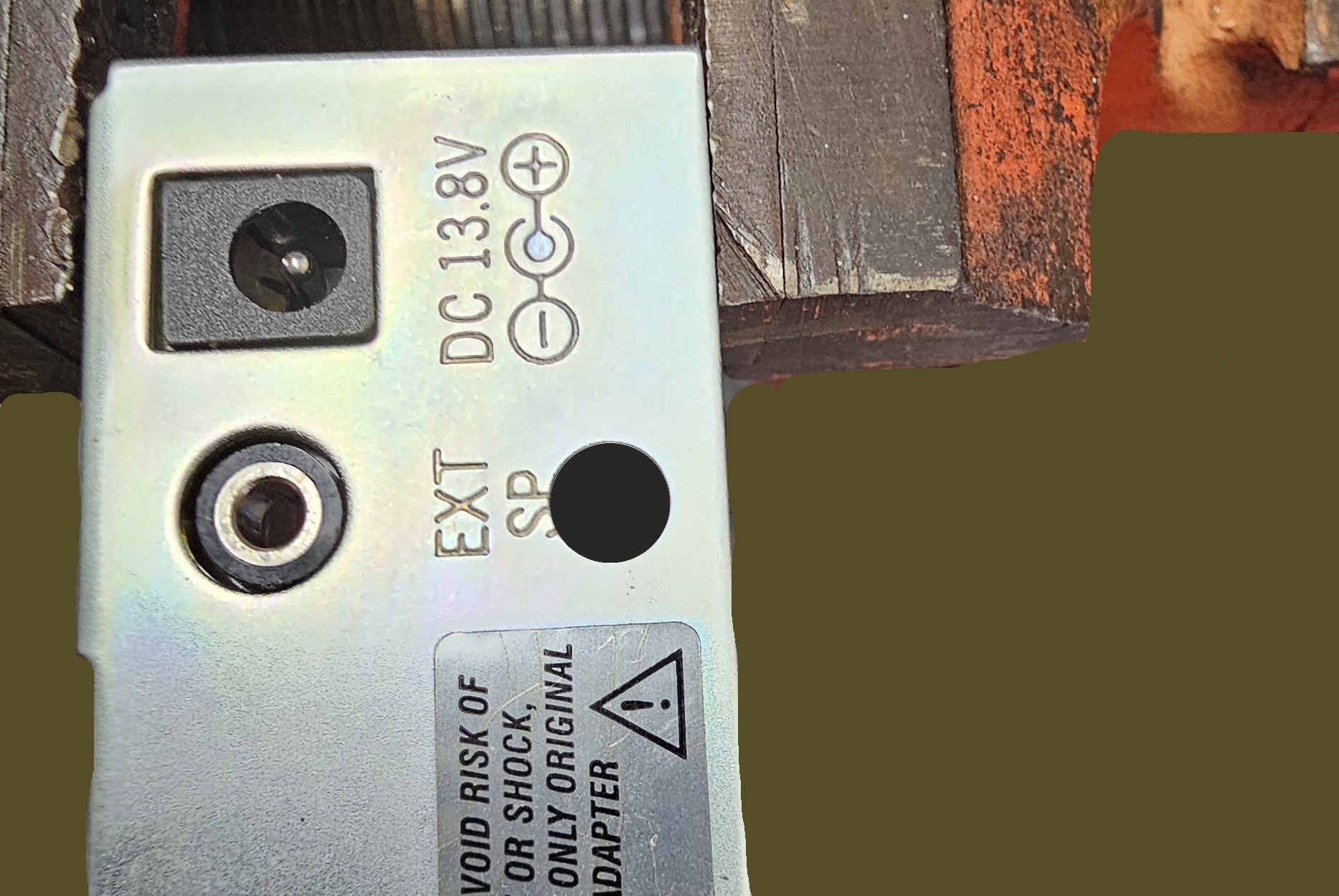
Hole drilled - outside view - shown enlarged.
(Click photo to show a larger image)
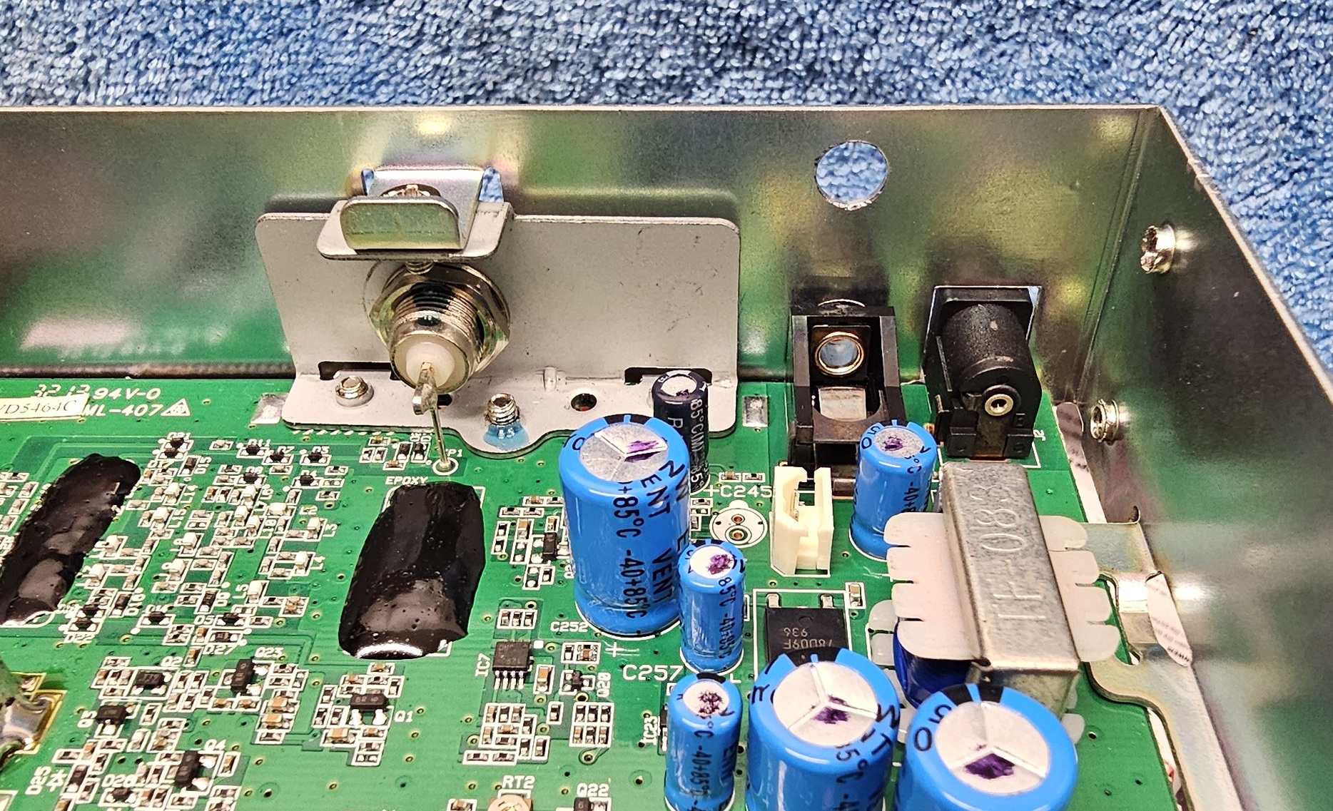
Hole drilled - inside view - shown enlarged.
(Click photo to show a larger image)
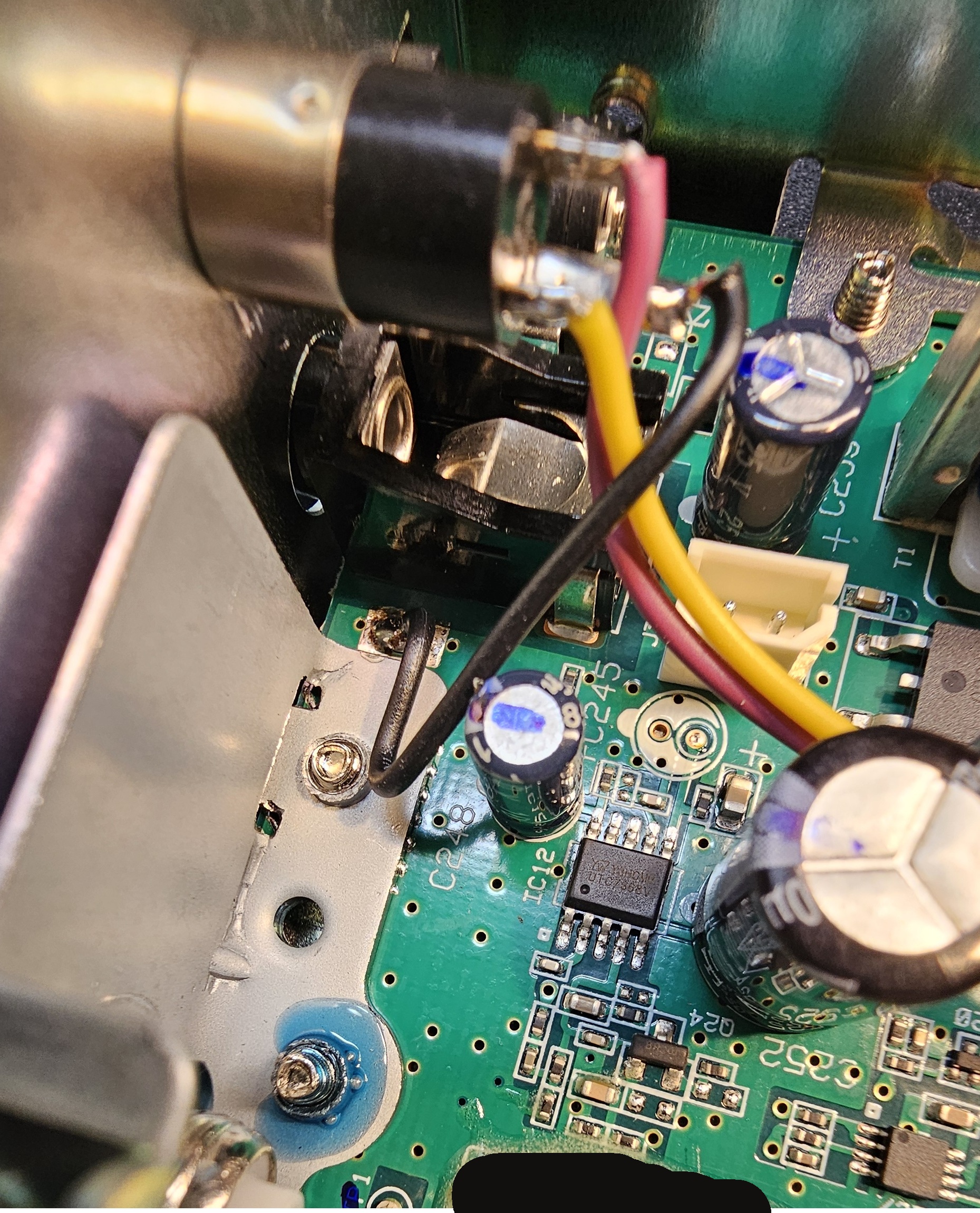
Jack installed - shown enlarged.
(Click photo to show a larger image)
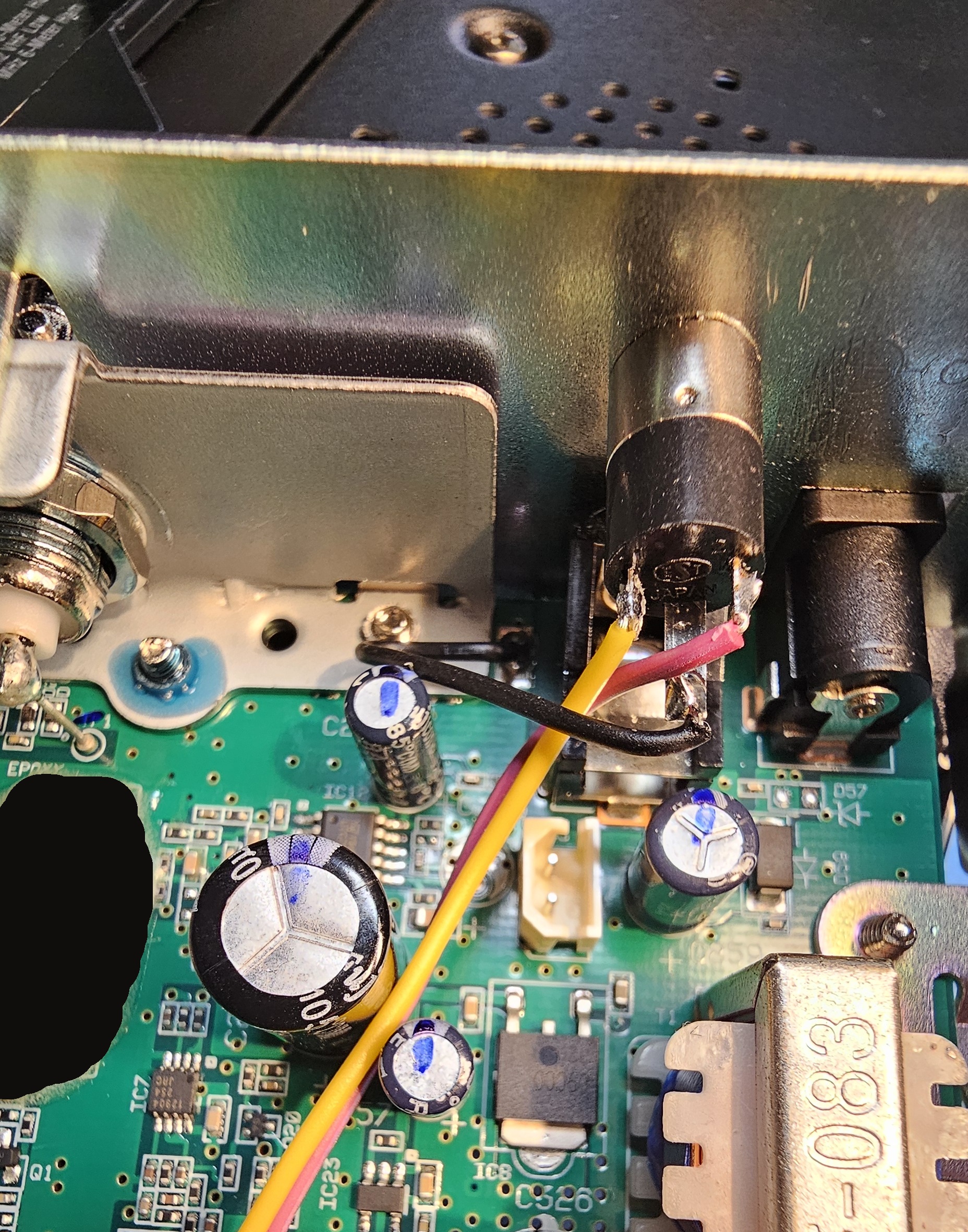
Jack ground connection - shown enlarged.
(Click photo to show a larger image)
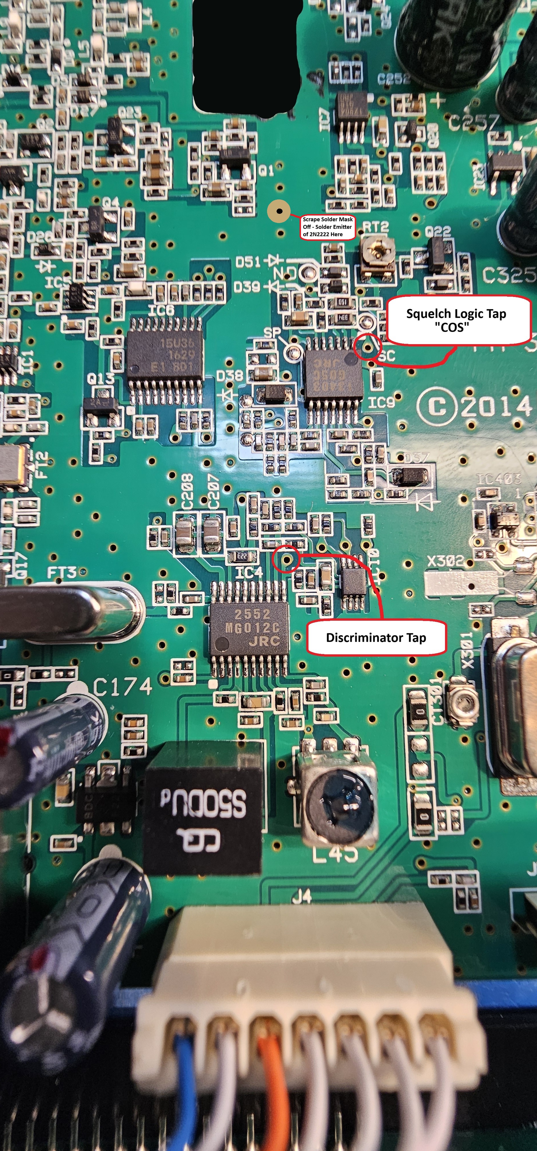
Discriminator & COS connections - shown enlarged.
(Click photo to show a larger image)
2N2222 connections - shown enlarged.
(Click photo to show a larger image)
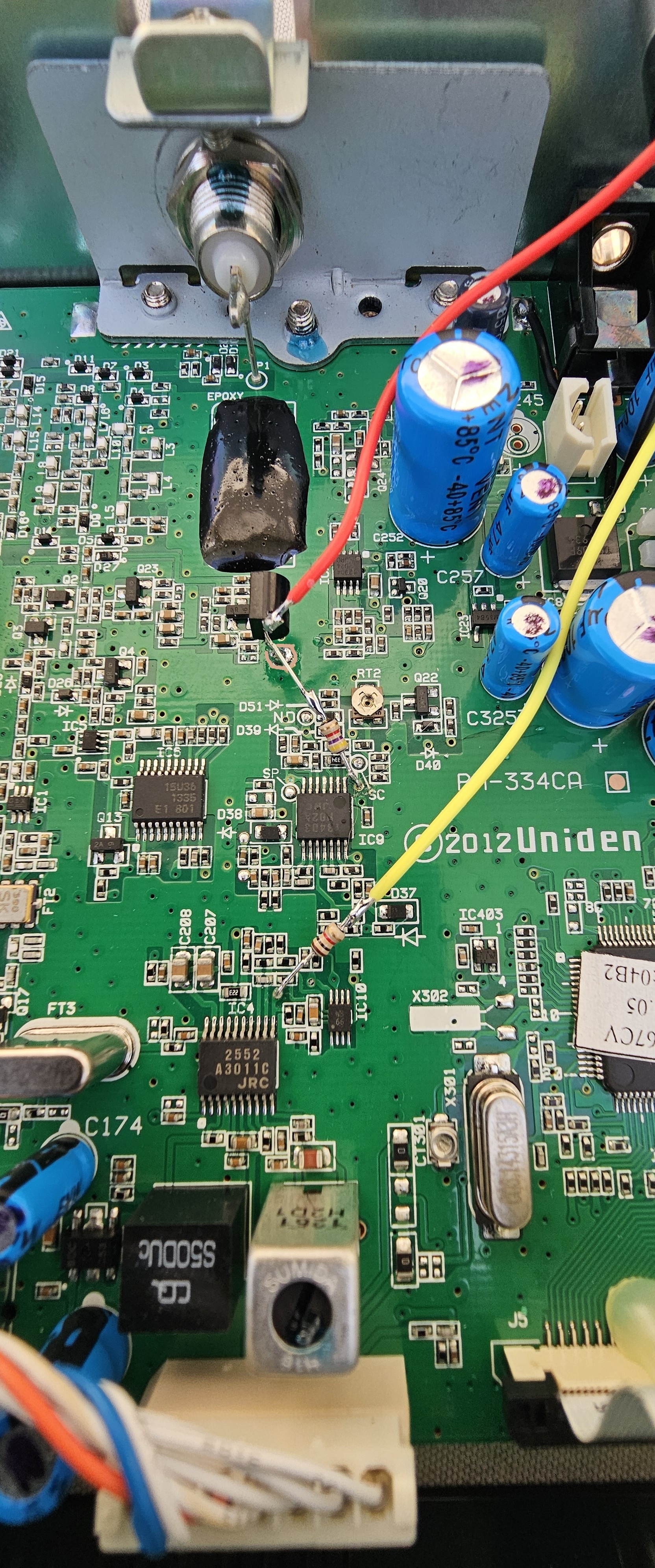
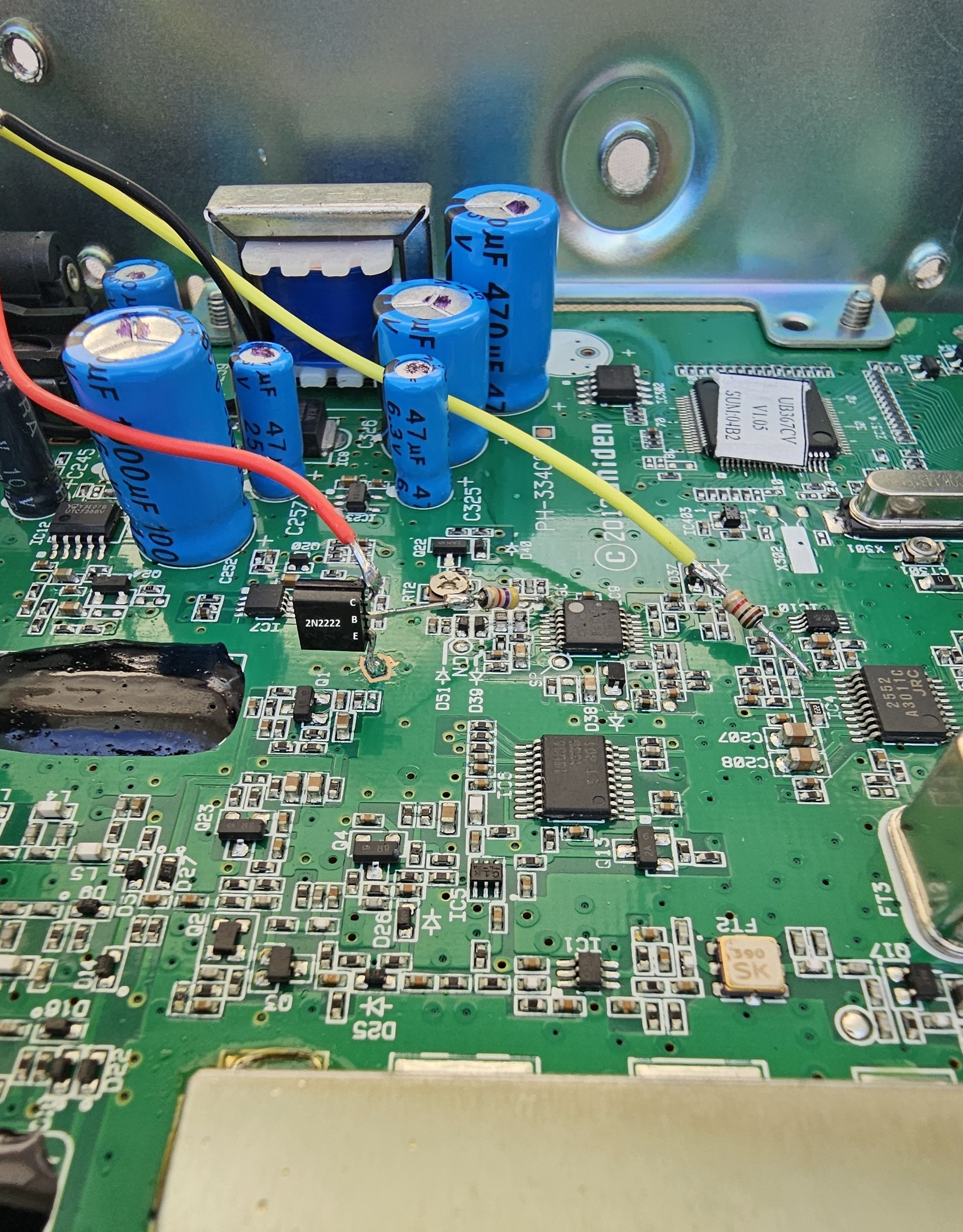
2N2222 connections - different view - shown enlarged.
(Click photo to show a larger image)
Modification:
Please read the instructions through to the end at least once.
This will keep you from jumping to conclusions and making an error that might
be difficult to recover from. Use the photos above to help you position the jack and wires /
resistors.
Mark a place to center punch the rear panel at 1/4" up from the bottom edge of the rear panel and centered on the external speaker jack (left and right). Center punch this location to allow a pilot hole to be drilled. Drill a 1/8" pilot hole where you center punched the rear panel. Be careful not to come in contact with any components with your drill or bit. Then, expand the hole to 1/4" to accommodate the 1/8" (3.5mm) chassis mount stereo jack.
Install the 1/8" jack into the hole you drilled.
Connect a wire from ground of the circuit board to the ground lug of the jack. The ground lug is the longer silver connection of the three. There is a convenient spot on the top of the circuit board between the speaker jack and some tinwork of the rear panel. See photos.
Connect a (yellow) wire of sufficient length from the tip lug of the jack to the discriminator tap on the circuit board through a 1k resistor. The tip lug is the short silver connection on the jack. The discriminator tap is a trace leading from pin 11 of the JRC2552 IC. This connection rides at about 1.2VDC with an "on frequency" signal of sufficient quieting, and shows discriminator noise on a no signal condition, and a sine wave when the receiver is hearing a signal with a modulating tone. Use an oscilloscope and the photo above to identify the location.
Cut the leads of the 1k resistor to approximately 1/2" long (each side - 1/2" long). Insert one lead of the resistor into the tiny hole in the circuit board and solder. This is more difficult than it looks because the solder mask may have clogged the hole. A tiny drill bit of the correct size (0.5mm) rotated by hand will clean out the hole, and allow a solid / reliable connection to be made by soldering the short resistor lead into the hole. Don't allow the lead to stick through the board a lot - just a little bit. Then strip and solder the yellow wire to the free resistor lead, trimming the length of the wire if necessary for shortest length.
A 2N2222 transistor is installed by connecting its emitter to the ground plane of the circuit board at a convenient location. Connect a (red) wire of sufficient length from the ring lug of the jack to the collector lead of the 2N2222 transistor. The ring lug is the short gold connection on the jack. The squelch logic (COS) tap is connected to the base of the transistor through a 4.7k resistor. The squelch logic (COS) tap is a trace / hole beside a 330k (334) surface mouunt resistor close to pin 1 of the JRC13403 IC. This connection transitions from (approximately) 0V to 3.3V between squelched and unsquelched. Use a volt meter (DMM) and the photos above to positively identify the location.
See the photos above for a suggested location to carefully scrape off the green solder mask to allow solder to stick. Then, install a 2N2222 transistor by connecting its emitter to the ground plane of the circuit board. Cut the leads of the 4.7k resistor to approximately 1/2" long (both sides). Insert one lead of the resistor into the tiny hole in the circuit board, as shown above, and solder. This is more difficult than it looks because the solder mask may have clogged the hole. A tiny drill bit of the correct size (0.5mm) rotated by hand will clean out the hole, and allow a solid / reliable connection to be made by soldering the trimmed resistor lead into the hole. Don't allow the lead to stick through the board a lot - just a little bit. Connect the free end of the resistor to the base lead of the transistor by trimming the length and soldering it in place. Then strip and solder the red wire to the collector lead of the transistor, trimming the length of the wire if necessary for shortest length.
Parts -
1 - Quality 1/8" (3.5mm) stereo chassis mount audio jack.
1 - 2N2222 transistor.
1 - Red wire - ~2.25" long.
1 - Yellow wire - !3.25" long.
1 - 1k 1/8W resistor.
1 - 4.7k 1/8W resistor.
1 - 0.5mm Carbide drill bit - operate carefully by hand - they break very easily (DO NOT Rock).
Secure PayPal ordering is available on the FMDM-150M main page.
Email
Kevin Custer for support, ordering information, order by check, or support of this
exciting product.
Product of Masters Communications, all rights reserved.
Specifications may change without notice.
Images property of Kevin Custer - W3KKC
Board layout by Kevin Custer - W3KKC.
HTML December 16, 2025, W3KKC All Rights Reserved!