Custom Products for the Analog & Digital Radio Amateur Enthusiast

|
Custom Products for the Analog & Digital Radio Amateur Enthusiast |
|
Analog Meter Display (AMD)
Board
For Analog & Digital Two-Way Radio
Applications
Top side of FMDM-150M Analog Meter Display (AMD) circuit board - shown slightly enlarged.
(Click photo to show a larger image)
(Click photo to show a larger image)
(Click photo to show a larger image)
(Click photo to show a larger image)
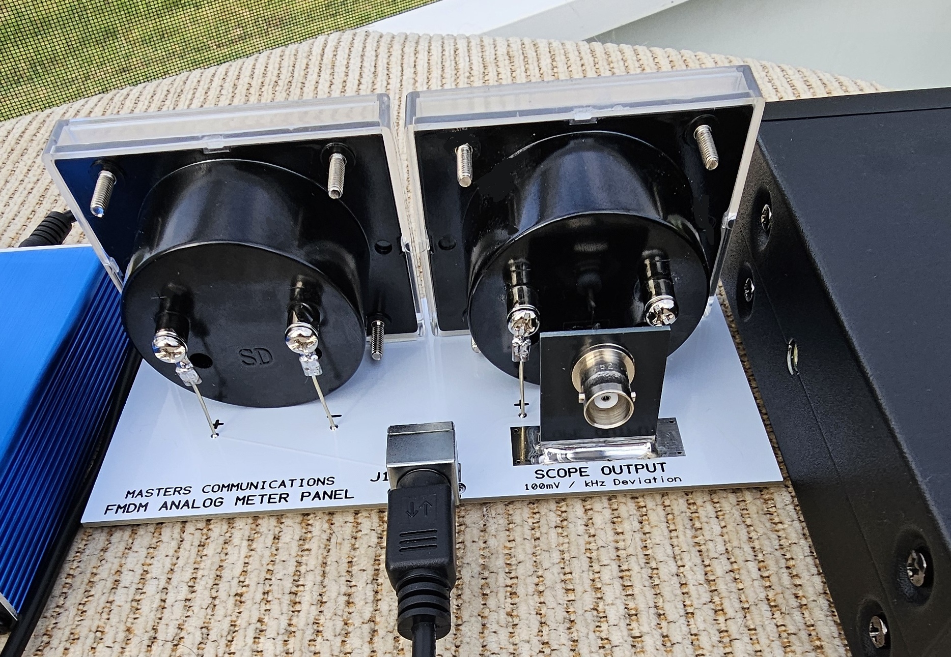
First, install the vertical board to the main board by installing a 1" piece of of #20 wire into each hole and bending them sharply at a 90 degree angle. This will make a tightly bent U shaped wire that the ends will be threaded into a pair of holes centered in the width of the bare area. Make sure the vertical board is seated down against the main board and tack solder. Adjust the angle of the vertical board so it's perpendicular to the main board. If its off - readjust it now, then solder the wires into the holes and trim the excess with a sharp pair of flush cutting pliers. Then - completely solder the front and back mating surfaces with a solder filet to make a strong / stable mechanical connection. This takes a good bit of heat and a lot of solder. Clean off the flux.
Position and install the BNC connector into the large hole in the vertical board with the connector facing out over the back edge of the Analog Meter Display board. Then install the tooth washer and nut on the opposite side. Tighten the nut while keeping the orientation of the tabs on the BNC connector aligned vertically or horizontally, or however you prefer. Take a piece of #20 wire and make the connection from the BNC connector's center pin to the hole between the + and - of the Deviation Meter - soldering both securely.
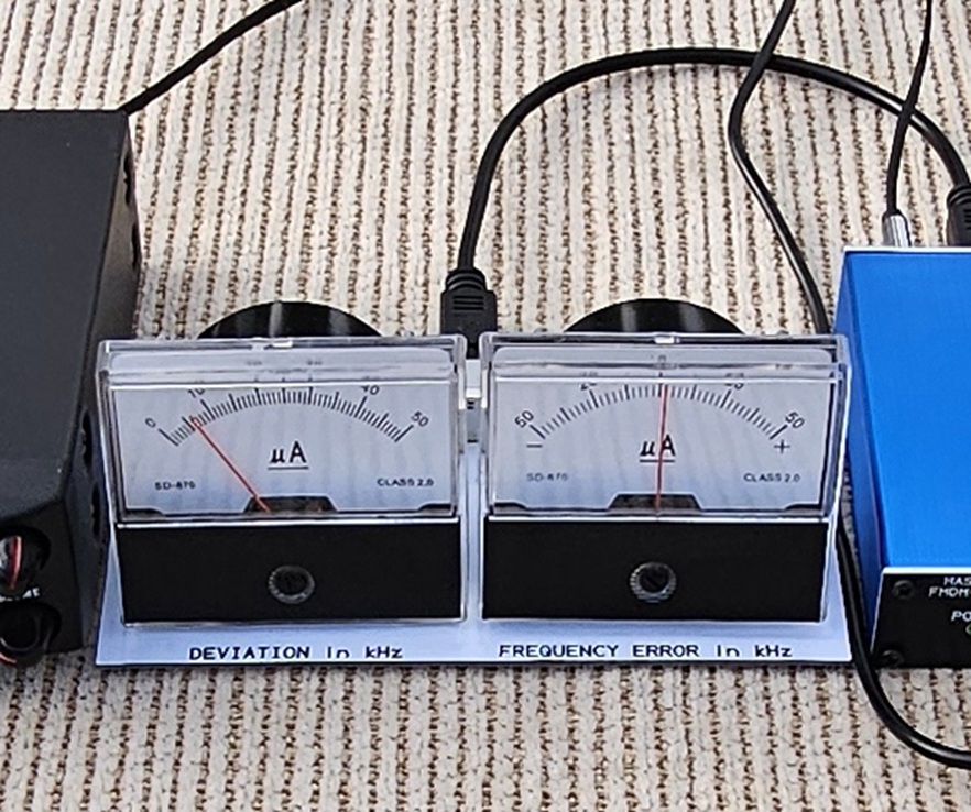
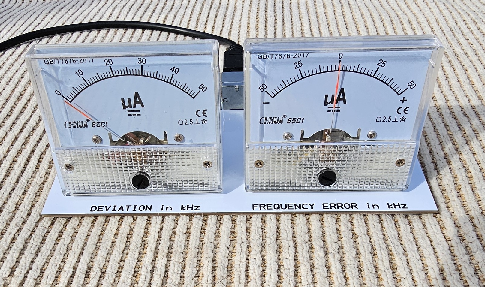
Meter wire placement is dictated by which meter sets were supplied to you. There are two different types of meters, Class 2 & Class 2.5. They are supplied in pairs. Between the two pairs, their bodies are a little different in length and diameter. Two sets of holes are provided for the meters positive and negative connections depending on which meter you have. Remember to review the photos of each meter type to help you with getting the meters properly positioned and wired up correctly.
Make four (4) 1.5" #20 wires and attach one #8 ring terminal to one end of each wire. Crimp, and optionally solder, the terminal to the wire. Install one wire and terminal loosely onto the positive and negative terminals of both meters using the supplied hardware. Depending on meter type, these could be screws, or nuts and washers. On the latter - use whatever hardware makes sense to you. I normally place the smaller nut on the stud and run it down the whole way by hand - Do NOT overtighten. Then place the ring terminal, a flat washer, and the larger nut.
This next step applies to either meter type.
Next - put a length of double sided attachement tape along the bottom of the meter face
along the back edge - length wise. Don't remove the red protective backing yet.
The meter will sit at a slight angle when correctly positioned. Dry fit the meter in place,
paying attention to the lettering on the front edge of the circuit board. Don't cover
the lettering when you actually mount the meter. Proper meter placement is slightly
behind the printed lettering - centering the meter face with the printing. The rear body
of the meter will sit directly on the white circuit board.
This next step applies to Class 2 meters:
If you have a Class 2 meter set, usually branded FLASH STAR, the wires will stick straight
down and go directly into the wider set of holes marked + and -. After you are satisfied
that you will get the meter in the correct position, remove the backing from the
double-stick tape and place the meter into its proper location. Make sure you have the
meter body seated against the circuit board and then solder the positive and negative
wires tightly into the white circuit board. Carefully tighten the screws on the meter.
Snug is good - do not overtighten.
This next step applies to Class 2.5 meters:
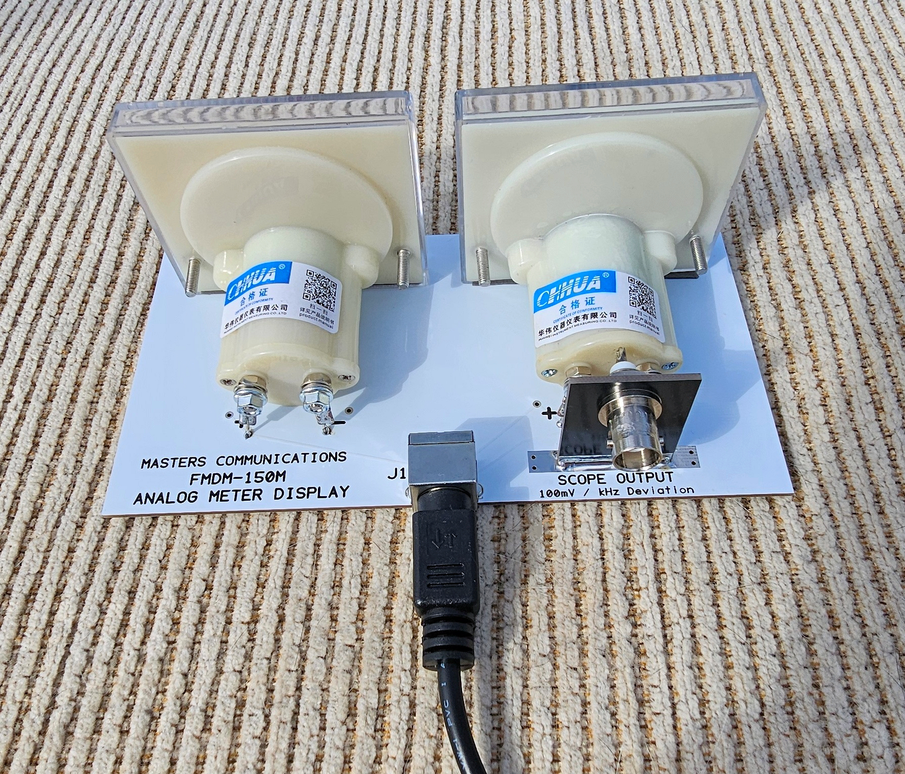
If you have a Class 2.5 meter set, usually branded CHHUA, the wires go into the narrower
set of + and - holes more toward the rear of the board. The Deviation Meter's connections
will end up close to, and centered over, the center conductor wire of the BNC connector.
The meter should be positioned so its positive and negative terminals are the same distance
from the BNC connectors' center pin / wire. After you are satisfied that you will get
the meter in the correct position, remove the backing from the double-stick tape and place
the meter into its proper location. Make sure you have the meter body seated down against the
circuit board and then solder the positive and negative wires into the white
circuit board. Carefully tighten the nuts on the meter. Snug is good - do not overtighten.
Next - install the Mini-DIN-6 connector into the top surface of the circuit board and solder all holes completely - especially the three mounting holes. Trim all soldered connections with a sharp pair of diagonal "flush" cutters.
Lastly - turn the meter panel over and install the four rubber feet into the corners of the bottom surface of the white circuit board.
Parts List:
If you purchased our kit, refer to the parts list and make sure you have all of the components
you need to build it.
Click here
for Parts List.
Support Documentation
Click here for AMD support documentation.
Installation:
This device is intended to be installed beside the AMU and connected with a short
male to male Mini-DIN-6 cable (supplied).
Secure PayPal ordering is available on the FMDM-150M main page.
Email
Kevin Custer for support, ordering information, order by check, or support of this
exciting product.
Product of Masters Communications, all rights reserved.
Specifications may change without notice.
Images property of Kevin Custer - W3KKC
Board layout by Kevin Custer - W3KKC.
HTML December 7, 2025, W3KKC All Rights Reserved!