Custom Products for the Analog & Digital Radio Amateur Enthusiast

|
Custom Products for the Analog & Digital Radio Amateur Enthusiast |
|
Analog Measurement Unit (AMU)
For Analog & Digital Two-Way Radio
Applications
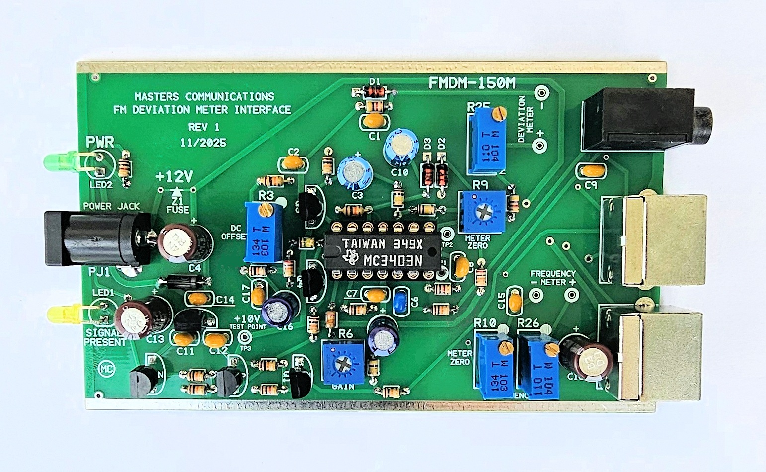
Top side of FMDM-150M Analog Measurement Unit (AMU) circuit board - shown slightly enlarged.
(Click photo to show a larger image)
Please read through this article at least once before starting
the calibration procedure.
It will bring your attention to things that need to be done in order to prevent damage to
the analog meters because of an uncalbrated condition - slamming the meter movements to their
extremes. While these meters aren't overly fragile, continuous extreme energy can hurt them.
The unit will need to be out of its case to perform calibration.
Required Equipment for Calibration:
Clean +12VDC regulated power supply.
RF signal generator with known carrier frequency accuracy and tone generation (modulation) in kHz.
DMM capable of reading DC voltage extremely accurately.
Oscilloscope capable of accurately measuring AC (audio) & DC (bias) levels up to several VDC.
Jewelers screwdriver or "tweaker tool" of the correct size to adjust the potentiometers.
(1) Calibration of the FMDM-150M Analog Measurement Unit (AMU)
Start by applying +12VDC at the coaxial jack - but don't connect up any other cables to the
unit at this point. Ground is available at the tinned rails along either side of the circuit board.
Take voltage readings at the +10V and +12V test points. The +12V test point is either
side of the Z1 fuse near the coaxial power jack. The +10V test point is TP3. The voltage at
TP3 can be anywhere from 9.75V to 10.05VDC and should be very stable. The exact amount is not critical
as long as it's between these two values and is stable. The 12V reading should be between
11.5 and 12.5VDC and again the exact amount is not critical as long as it's between these
two values and is stable.
(2) If the voltages at these test points check out - connect the AMU to a modified BC355N scanner using the short 3.5mm stereo cable (supplied). Turn on the scanner and program a frequency within the frequency range of your calibrated signal generator. DO NOT generate or apply a signal yet to the antenna jack. The exact frequency is not important because the AMU opertes at the receivers discriminator which its DC level is the same regardless of the frequency being measured. Without a signal being generated, adjust the squelch control on the scanner open and closed alternately hearing noise from the scanners speaker. Adjust the volume control on the scanner as necessary to hear the noise. When noise is heard - the Yellow "Signal" LED should illuminate on the front panel of the AMU, and go out when the squelch control is adjusted sufficiently to mute the noise. This verifies the COS signal is working correctly in the scanner and the mute circuitry in the AMU is mostly working.
(3) If the Signal LED is operating properly when the receiver's squelch is opened and closed, set the squelch closed and set R6 (the 3/4 turn GAIN control) to 50% rotation. Connect either or both the Analog Meter Display and Digital Meter Display using the supplied short Mini-DIN-6 cable(s), and an oscilloscope (AC coupled) to the AMD with a short coaxial cable. The oscilloscope should display discriminator noise with no signal being received - even though the Signal LED is off. The oscilloscope output is biased at 4.0VDC and this voltage changes with the change in RF carrier frequency - and is why the scope needs to be AC coupled to see the audio level - Peak-to-Peak.
(4) At this point - nothing is calibrated, and the meters could be displaying anything - even slammed against a stop. We should try to work through the next step rapidly to get the AMU calibration close and allow the needle meters to get into more normal positions. These steps will get the analog meters positioned for a more accurate final calibration.
(5) Apply an on-frequency carrier signal of sufficient signal strength from the output of the signal generator to the antenna jack of the scanner. DO NOT apply any modulation yet. I generally use a signal that is at least -70dBm connected directly to the ANT input to insure the receiver is full quieting. Adjust R3 (the multi-turn DC OFFSET control) for a reading of 4.0 VDC at TP1. This test point is near pin 7 of the op-amp. Set R9 (the 3/4 turn METER ZERO control) so the Deviation Meter reads zero. Adjust R10 (the multi-turn Frequency Meter Zero control) so the Frequency Error Meter reads centered (zero).
(6) Now apply a 1kHz modulating tone at 5kHz deviation on the carrier signal from the RF signal generator. Adjust R6 for a reading of 500mV P-P of the audio sine wave on the AC coupled oscillloscope input. Alternately readjust R3 and R6 to achieve 4.00V at TP1 and 500mV P-P at the oscilloscope. These two controls have some interaction, but you should achieve these exact values in a few passes.
(7)
Now we'll adjust (calibrate) the Deviation Meter.
Turn off the 1kHz modulation. Set R9 (the 3/4 turn Deviation Meter Zero control) so the
Deviation Meter reads zero (0). Turn the 1k / 5 kHz modulation back on and adjust R25
(the multi-turn Deviation Meter Multiplier control) so the Deviation Meter reads "50"
(5.0 kHz). Do this step again until you achieve these values with and without modulation.
(8) If your signal generator has the ability to adjust the modulating tone frequency, set it anywhere between 50Hz and 3000Hz and generate a 5kHz deviated signal. The Deviation Meter should read 5.0kHz within 1 - 2% at any frequency between 50 and 3000Hz. If you like, go to further extremes of 30Hz and 5400Hz keeping the deviation of the generator accuratey set to 5kHz. The Deviation Meter should read 5.0kHz within 10% between 30 and 5400 Hz.
(9)
Now we'll adjust (calibrate) the Frequency Error Meter.
Apply an on-frequency carrier signal of sufficient signal strength from the output of
the signal generator to the antenna jack of the scanner. DO NOT apply any modulation
at this time. I generally use a signal that is at least -70dBm connected directly to the ANT input
to insure the receiver is full quieting. Adjust R10 (the multi-turn Frequency Meter Zero
control) so the Frequency Error Meter reads centered (zero). Now adjust the signal generator's
frequency to minus 5kHz of the frequency set on the scanners display and adjust R26 (the
multi-turn Frequency Meter Multiplier control) for a left reading of "50" 5.0kHz. Reset
the generator to remove the frequency offset and readjust R10 for center "0". Alternately
adjust these two controls until you achieve these two meter values. Check the accuracy
by adjusting the frequency offset of the generator to positive 5kHz and make sure the
meter reads a right reading of "50" 5.0kHz. Correct balance of R10 and R26 will provide
a frequency error that's within 1 - 2%.
This concludes the calibration procedure of the FMDM-150M AMU.
Secure PayPal ordering is available on the FMDM-150M main page.
Email
Kevin Custer for support, ordering information, order by check, or support of this
exciting product.
Product of Masters Communications, all rights reserved.
Specifications may change without notice.
Images property of Kevin Custer - W3KKC
Board layout by Kevin Custer - W3KKC.
HTML December 7, 2025, W3KKC All Rights Reserved!