Custom Products for the Analog & Digital Radio Amateur Enthusiast

|
Custom Products for the Analog & Digital Radio Amateur Enthusiast |
|
Digital Meter Display (DMD)
For Analog & Digital Two-Way Radio
Applications
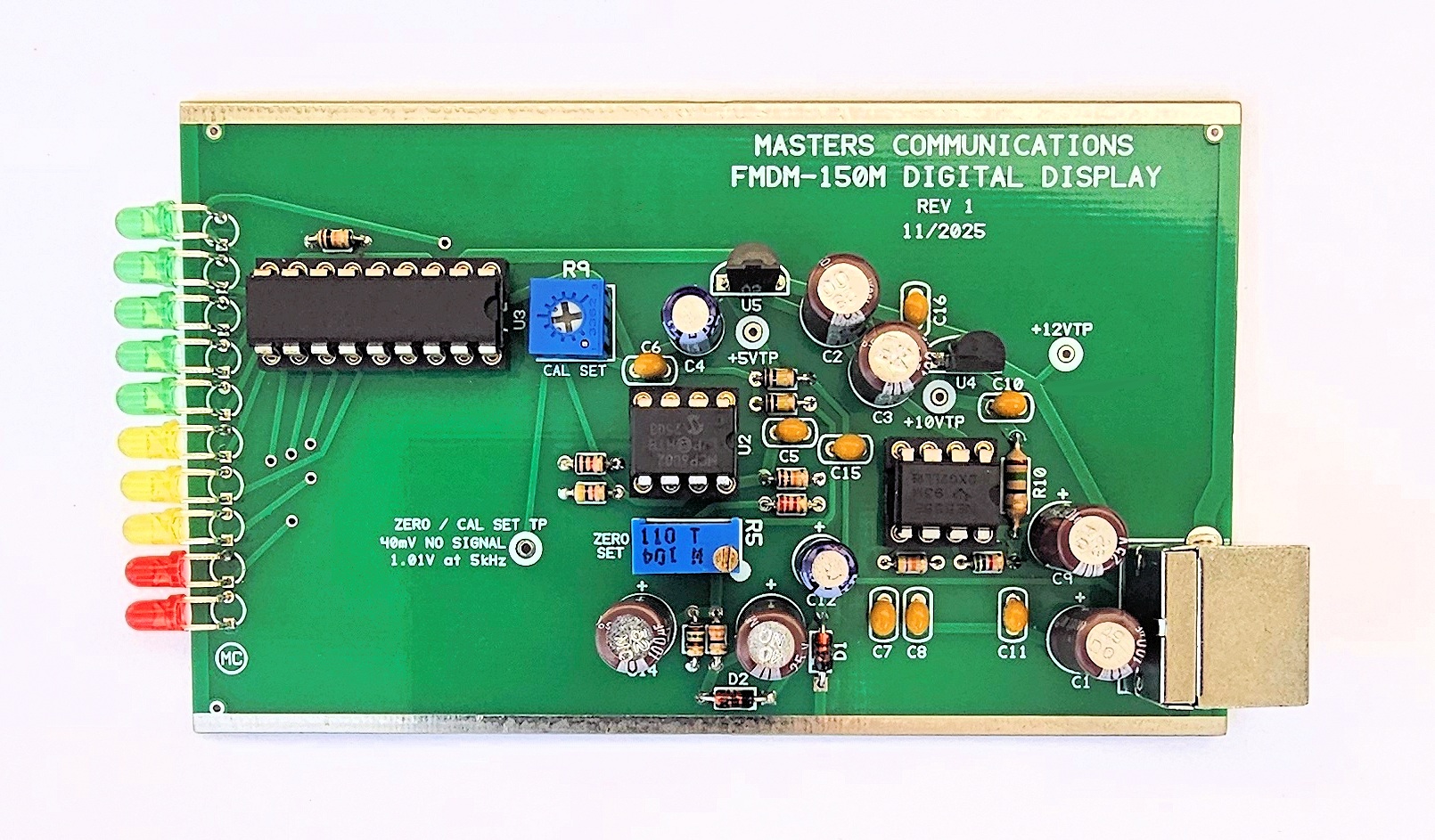
Top side of FMDM-150M Digital Meter Display (DMD) circuit board - shown slightly enlarged.
(Click photo to show a larger image)
Required Equipment for Calibration:
A fully functional FMDM-150M with calibrated AMU and modified BC355N scanner.
RF signal generator with known carrier frequency accuracy and tone generation
(modulation) in kHz.
DMM capable of reading DC voltage extremely accurately.
Jewelers screwdriver or "tweaker tool" of the correct size to adjust the potentiometers.
Calibration of the FMDM-150M Digital Meter Display (DMD)
Connect the DMD to the AMU with the supplied short Mini-DIN-6 cable. Connect the AMU to a
scanner. Apply +12VDC at the coaxial jack of the AMU and scanner and turn everything on.
Ground is available at the tinned rails along either side of the circuit board. Take
voltage readings at the +12V, +10V and +5V test points. The voltage at the +10 and +5V
test points can be anywhere from 9.75V to 10.05VDC and 4.9 and 5.1V respectively, and
should be very stable. The exact amount is not critical as long as it's between these
values and is stable. The 12V reading should be between 11.5 and 12.5VDC and again the
exact amount is not critical as long as it's between these two values and is stable.
The Digital Meter Display also uses a negative voltage which is generated by the 555 circuitry. -5.85 VDC should be present at the non-banded end of D2. The exact amount is not critical as long as it is close to this amount and is stable.
If the voltages at these four test points check out - program a frequency into the scanner that's within the frequency range of your calibrated signal generator. The exact frequency is not important. DO NOT generate or apply a signal yet to the antenna jack. Without a signal being generated, and the squelch closed adjust R5 for 40mV DC at the Zero / Cal Set Test Point.
Apply an on-frequency carrier signal of sufficient signal strength from the output of the signal generator to the antenna jack of the scanner. DO NOT apply any modulation yet. I generally use a signal that is at least -70dBm connected directly to the ANT input to insure the receiver is full quieting. Remeasure the voltage at the Zero / Cal Set Test Point. Readjust R5 (if necessary) for 40mV DC at the Zero / Cal Set Test Point. No LED's should be lit.
Now apply a 1kHz modulating tone at 5kHz deviation on the carrier signal from the RF signal generator. Adjust R9 for 1.01VDC at the Zero / Cal Set Test Point. All but the last two (red) LEDs should be illuminated.
Adjust the deviation for 6.2 kHz and make sure the last two LED illuminate.
Now - set the signal generators deviation to match each level indicated by the steps of the LEDs. Each one should illuminate within 2% of the value on the front panel. If not - go through the calibration procedure again.
This concludes the calibration procedure of the FMDM-150M DMD.
Secure PayPal ordering is available on the FMDM-150M main page.
Email
Kevin Custer for support, ordering information, order by check, or support of this
exciting product.
Product of Masters Communications, all rights reserved.
Specifications may change without notice.
Images property of Kevin Custer - W3KKC
Board layout by Kevin Custer - W3KKC.
HTML December 7, 2025, W3KKC All Rights Reserved!