Custom Test Equipment for the Analog & Digital Radio Amateur Enthusiast

|
Custom Test Equipment for the Analog & Digital Radio Amateur Enthusiast |
|
Detailed Description:
This test equipment provides a way to accurately and directly measure and display the amount of
FM deviation on several commercial, amateur radio, and GMRS bands without needing a computer or
complex software. It's extremely easy to use and is intended for amateur / hobbyist use
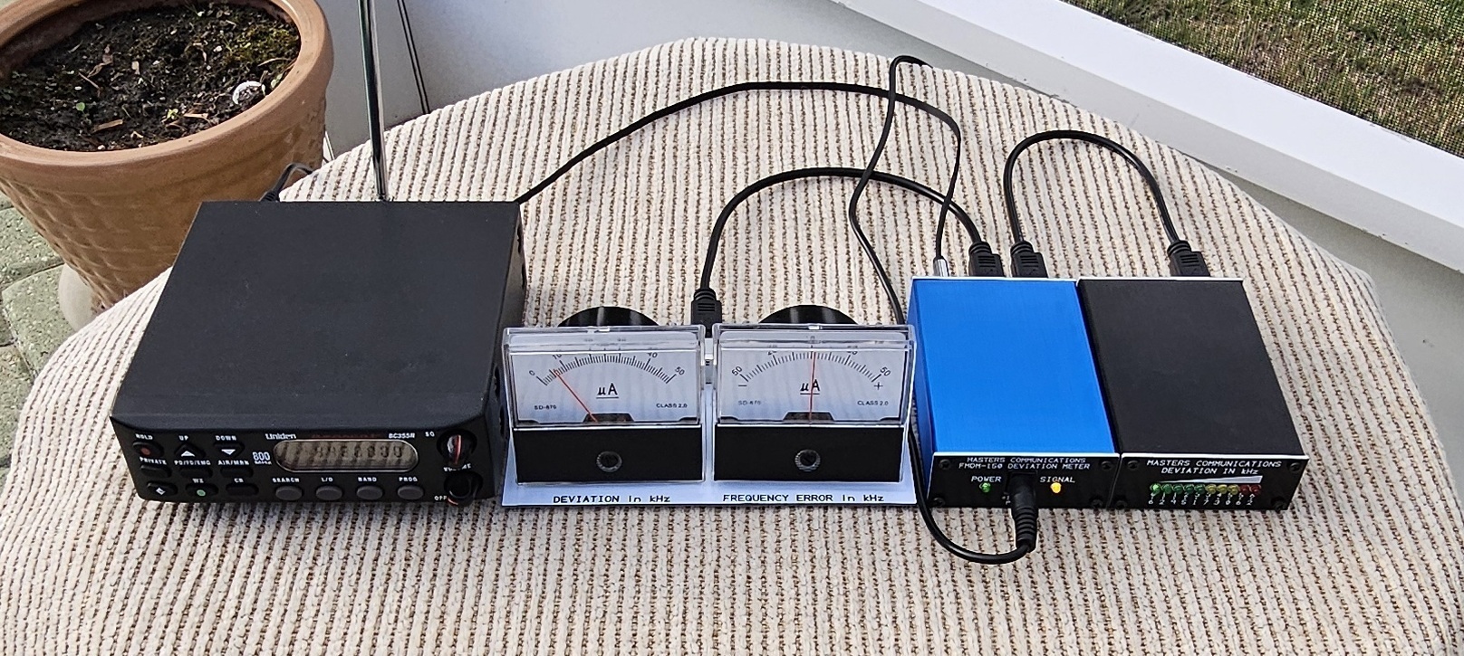
where affordability is a requirement. It uses a curent model Uniden scanner for the receiver,
providing frequency agility and channel memory storage. Other modules are connected to the
scanner and make up a complete deviation measurement system. The scanner is slightly modified by
adding a 3.5mm stereo jack to gain access to discriminator audio, squelch logic and ground.
We chose the Uniden BC355N, because it provides a very flat frequency response and is very stable.
This allows relatively inexpensive and less complex circuitry to be connected that accurately
measures and displays deviation on three different display methods; analog needle meter, digital
LED display, and (an oscilloscope [not included]). A second analog meter shows frequency error.
The operation of the scanner is not impacted by the modification, and it can be used to monitor
the audio from its internal speaker or a better external communications type speaker (not included).
The squelch logic signal is used to mute the audio going to the analog and digital deviation meters so they aren't pinned to maximum movement or maximum display under a no-signal condition - as long as the scanners squelch control is set appropriately. Additionally - a yellow LED on the Analog Measurement Unit (AMU) indicates when a valid signal appears at the receiver with a signal level sufficient to open the squelch. The oscilloscope output on the analog meter panel is DC coupled and not muted by the squelch circuitry. It shows raw discriminator noise under a no-signal condition, and the modulating waveform on a valid signal. The receiver is easily set to the desired frequency with the buttons on its front panel and is displayed numerically on its LCD display.
The scanner is capable of receiving all NBFM channels in the 10 Meter, 6 Meter, 2 Meter, UHF, and 900 MHz amateur bands, and the commercial VHF (high-band) and UHF bands. 220 MHz is not covered by this unit. A complete list of frequency coverage is provided on the main page. Several scanners were tested while developing this measurement system and this one was chosen for its lower cost, availability both new and used, excellent linearity, wide frequency response, and good stability. The receiver is very sensitive and doesn't require a direct or coupled RF connection to the radio or repeater being measured - as long as the signal is 'full quieting'. The telescoping antenna is generally sufficient for most applications.
The modular construction allows for separately purchasing only the items you need / want, or can afford. It's great for clubs or guru individuals that help with repeaters or digital data installations like Winlink Gateways. While it doesn't take the place of a real communications service monitor - it provides a way to accurately measure deviation from a FM transmitter within the frequency range of the Uniden scanner / receiver.
Modification of a new scanner will undoubtedly void its factory warranty. Masters Communications will provide a 90 day limited warranty for new scanners that are modified by us. Nothing says that you need to purchase a brand new scanner. While this system was developed for use directly with the newest "367E" series Uniden Bearcat BC355N, it will work correctly with older ones. Older units may require a different squelch logic connection and an additional 2N2222 transistor to invert the squelch logic signal polarity. We provide all of the modification details for the different series going back to 2010. Used scanners sometimes sell for less than $50.00 while new BC355N's sell for around $140.00 not including the discriminator tap / squelch logic jack modification (parts and labor).
Nothing says you need to buy or use a Uniden BC355N scanner. Any receiver that uses the NJM2552 I-F / demodulator IC should work well with the analog measurement unit. There are a few others we know about like the Uniden BC360CLT, the Radio Shack PRO-136 (which is identical to the Uniden BC360CLT) the Uniden BC370CRS, and, the Uniden BC355C. The circuitry has also been tested with the TK10420 demodulator as in the original article and will work successfully with scanners using that IC. The Radio Shack PRO2010 and PRO-2021 have been tested and are known to work. Note - we've not tested any other models and can't guarantee or imply that they will work and give the same measurement accuracy, but they probably would as long as they have either a NJM (JRC) 2552 or TK10420 demodulator IC. Adding a "discriminator tap" to scanning receivers is the whole purpose of the "Discriminator" website. This is where we found the information we used to modify the Uniden Bearcat BC355N. While this page is for a BC355C, the BC355N chassis is very similar, and the information is pertinent. Unfortunately - there are no scanners that we're aware of that cover the 220 amateur band that use the JRC NJM2552 I-F / Demodulator IC. We chose the BC355N because it covers the most common bands, it's readily available and incredibly stable and linear - - making it an excellent choice to drive a deviation measurement system.
The Analog Measurement Unit (AMU) is based on a construction article that appeared on the Repeater Builder® website some time ago. The AMU has an all aluminum case that is available in three colors - black, red, and blue. The designers circuitry has been duplicated many times and has stood the test of time. The FMDM-150M AMU is a variation of this circuitry and includes a few things that were not included in the original article / concept.
The original circuitry was driven by a legacy Radio Shack PRO-2021 scanner that uses a TK10420 I-F / demodulator that chip which has a different output level and biasing point as compared to the Uniden Bearcat BC355N. The latter uses a NJM2552 demodulator chip. Both are compatible with the AMU, but each requires the AMU to be calibrated using a different method. Modification and calibration procedures are provided for both demodulator types. For the BC355N, this calibration results in an AC oscilloscope output that is 100mV AC per kHz of deviation at the BNC connector. The AMU (as supplied) will also work with a Radio Shack PRO-2010 or PRO-2021 scanners. and when calibrated provides 400mV AC per kHz of deviation at the BNC cionnector.
The Analog Meter Display "panel" (AMD) is a rather simple type of display, constructed to be practical, accurate, and inexpensive. While not inherently rugged, it's not terribly fragile either. The panel includes a BNC connector and two analog meters - one for reading deviation and one for reading frequency error. Both meters are 50uA meter movements that have a 0 - 50 numbering scheme. The reading is taken directly and divided by 10. A full scale reading of 50 is therefore 5.0 kHz on either meter. The deviation meter is pretty self explanitory, and the frequency error meter is handy where netting a crystal or reference oscillator 'on frequency' is necessry. It is invaluable with crystal controlled radios. Also - the error meter allows you to check the calibration of the AMU by simply stepping the input frequency 5kHz above and below the programmed frequency of the scanner and seeing the frequency error meter read +/- 5kHz - each side of zero. A "zero" reading on the frequency error meter, therefore is the exact frequency shown on the scanners digital display.
The AMD's circuit board additionally has a rear mounted BNC female connector to take the DC coupled signal path (with recovered audio) to an oscilloscope. We have tested several of the the inexpensive (DSO) oscilloscopes with a plastic or pre-cut acrylic case found on eBay and AliExpress - and they work fine for this application. Unfortunately many of them require 9VDC to operate the unit, and that supply voltage is not available from any of the deviation meter components, but some oscilloscopes are supplied with their own power supply. An oscilloscope option isn't currently provided by Masters Commumications, but a short male to male BNC cable is available. Oscilloscopes are available from several sources like those already indicated, or even Amazon. Personally - I prefer an older CRT analog type here, but that's just me.
The BNC oscilloscope output on the AMD is available to connect any type of oscilloscope capable of displaying audio frequency signals (AC) with reasonable accuracy. Connection of many oscilloscopes require a male to male BNC cable, and a short (1.5 foot) cable is available from us for an additional cost. The analog and digital displays are only capable of showing total deviation. The AMU analyzes the output of the baseband detector, sums the positive and negative going peaks, and 'holds' them long enough for the meters to reasonably react. An oscilloscope display allows you to see positive and negative waveforms in real time. The oscilloscope output is DC coupled and shows signals that are on or off frequency, clean or distorted (on purpose or not) and shows any asymmetry (deviation that goes more positive than negative, or vice versa). This capability is invaluable for troubleshooting distortion in the audio path. One example is CTCSS tones that become distorted and sound much louder than they should - even at the correct deviation level (600 - 750Hz). Another example is audio that is high enough in magnitude to hit the speech limiter. This generally creates distortion that is acceptable for analog voice because is adds body and fullness, but that distortion is bad for digital data because it ruins the ability for fastest data transfer by creating a scattered constellation or unreliable decoding.
The "LED Bar-Graph" Digital Meter Display (DMD) is very rugged as compared to the analog meter panel. It reads deviation in the form of a 10 segment expanded bargraph made up of individual 3mm LEDs from 600Hz to 6.2kHz across the 10 LEDs using a custom front panel that indicates certain levels of deviation. The LEDs follow this color scheme - 1 thru 5 are green, 6 thru 8 are yellow, and 9 and 10 are red. The LEDs are driven by a LM3914N IC and is surrounded by other calibration components. This display is more granular as compared to the analog needle meter, but it's possible to adjust most transmitters' deviation using only this display. For example, the first LED would be lit solidly for proper CTCSS deviation at 600Hz. The fourth LED would be lit solidly for VARA FM Wide at 2.5kHz deviation. The fifth LED would be dimly lit for a 1200 baud packet system at 3kHz deviation, and a repeater would be set to fully illuminate the eighth LED at 5.0 kHz deviation under modulation peaks. The digital meter option doesn't provide a BNC output for the oscilloscope, but that signal is available on the "Analog Meters" Mini-DIN-6 connector on the AMU (pins 1 & 2), if the Analog Meter Panel is not connected to that port connector. A cable to connect an oscilloscope to this Mini-DIN-6 connector is NOT currently available and would need to be custom built.
This detailed explanation is a work in progress. If anything here is incomplete or unclear,
please email or call me and I'll work to resolve the ambigiuty or cause of confusion.
Online ordering of these components is available from the FMDM-150M Main Index Page.
Email Kevin Custer for ordering information, ordering by check, and/or support of this exciting product.
Product of Masters Communications, all rights reserved.
Specifications may change without notice.
Images are property of Kevin Custer - W3KKC
Board layouts by Kevin Custer - W3KKC
HTML December 4, 2025, W3KKC All Rights Reserved!