Custom Products for the Analog & Digital Radio Amateur Enthusiast

|
Custom Products for the Analog & Digital Radio Amateur Enthusiast |
|
I have photos below of the Radio Shack PRO-2021 but I don't have photos for the PRO-2010. Please refer to the Discriminator Tap site for photos of that scanner.
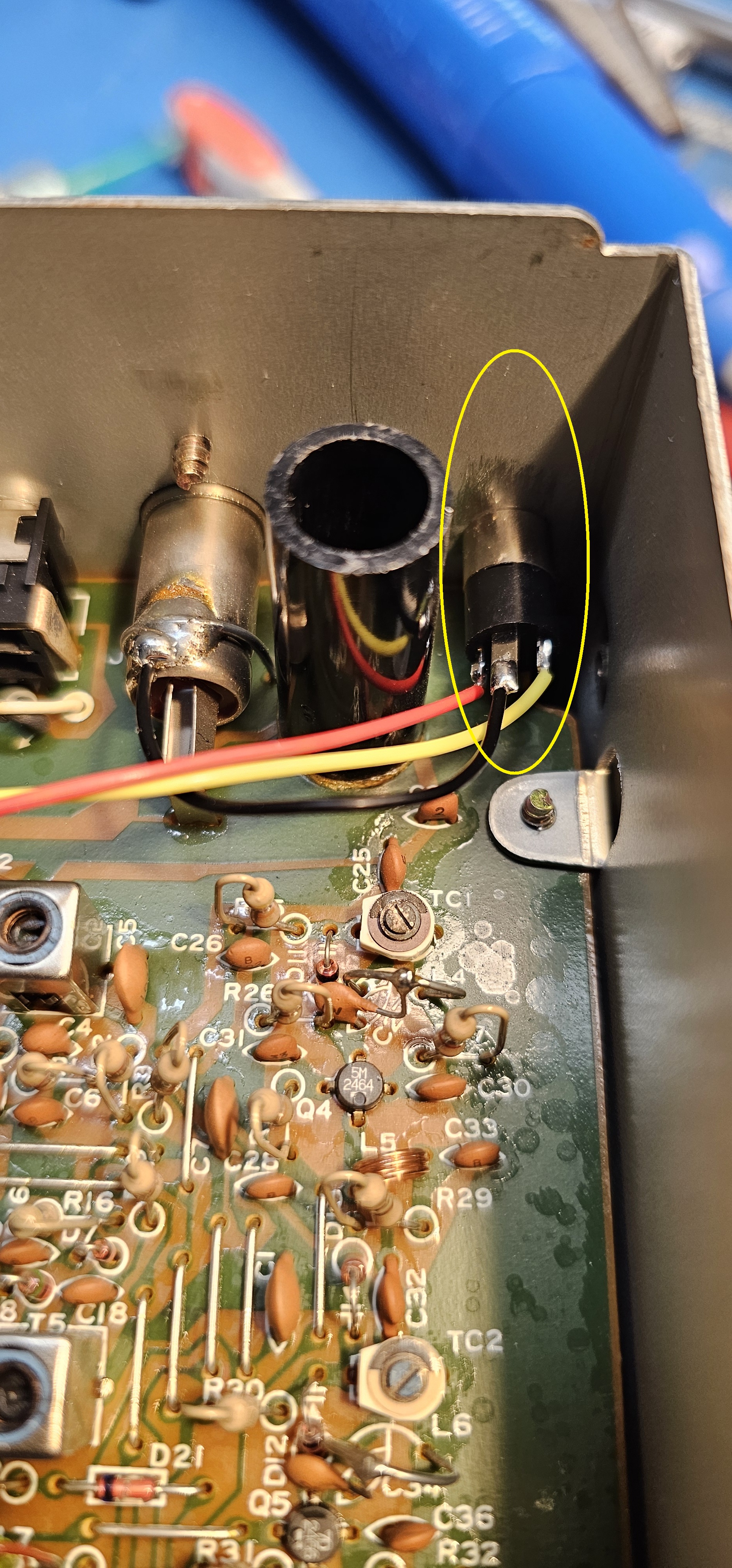
Rear Panel of Radio Shack PRO 2021 Scanner - jack installed - shown enlarged.
Jack installed - shown enlarged - NOTE ground connection.
(Click photo to show a larger image)
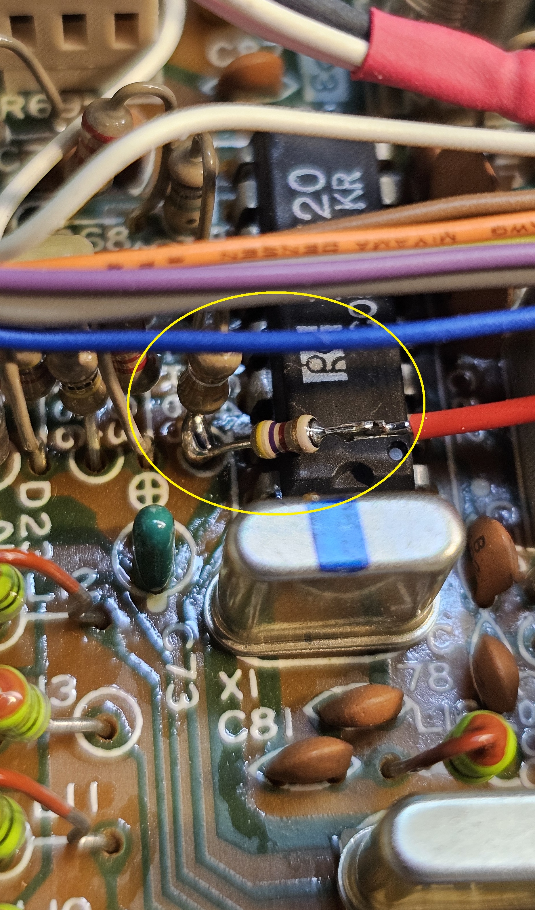
COS connection - shown enlarged.
(Click photo to show a larger image)
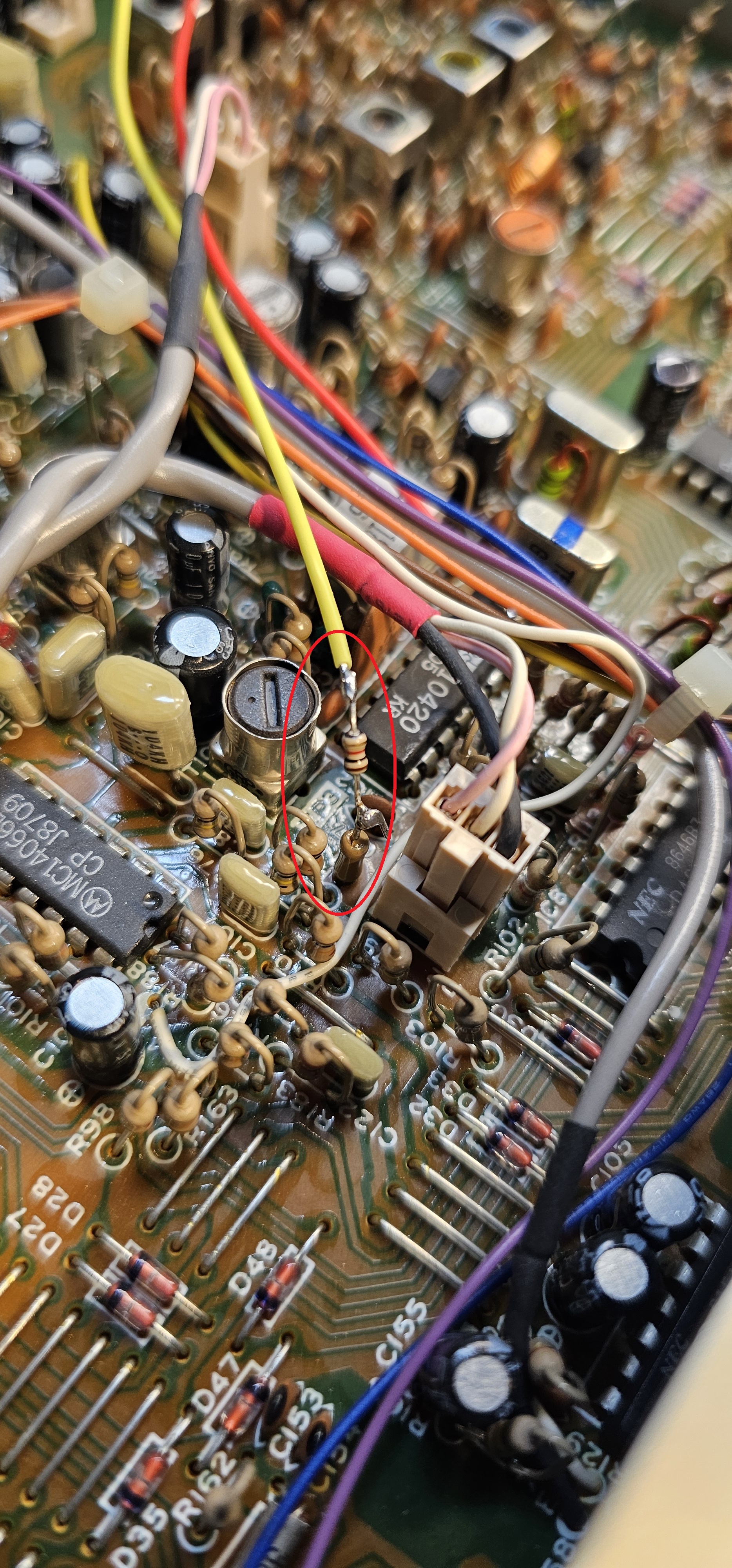
Discriminator connection - shown enlarged.
(Click photo to show a larger image)
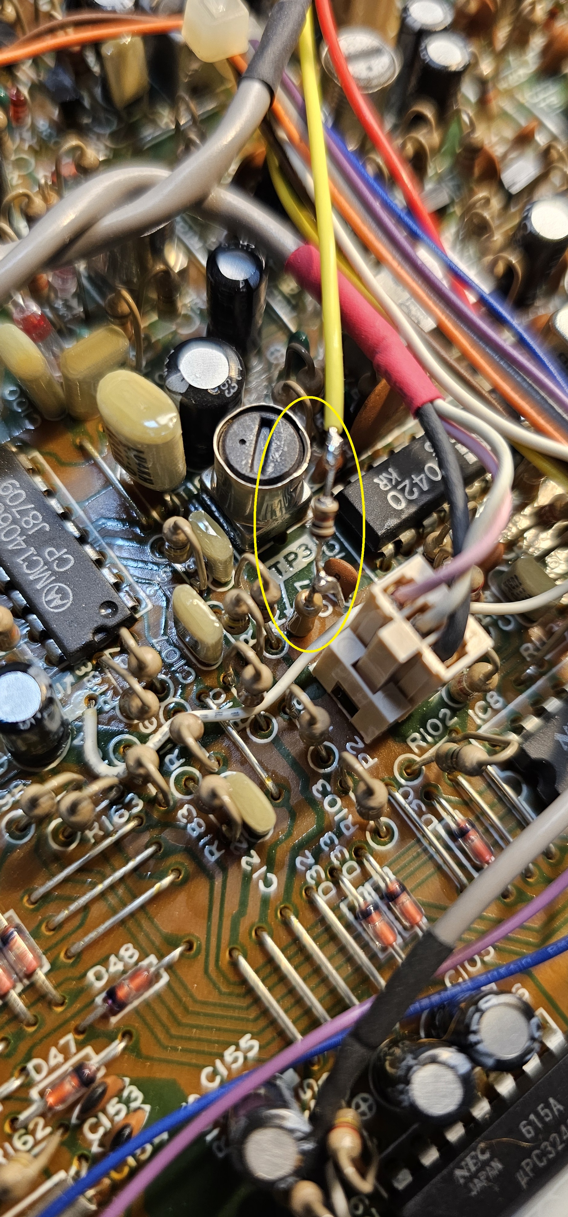
Discriminator connection - different view - shown enlarged.
(Click photo to show a larger image)
Modification:
Please read the instructions through to the end at least once.
This will keep you from jumping to conclusions and making an error that might
be difficult to recover from. Use the photos above to help you position the jack and wires /
resistors.
Mark a place to center punch the rear panel centered on the existing jacks, (left or right). Center punch this location to allow a pilot hole to be drilled. Drill a 1/8" pilot hole where you center punched the rear panel. Be careful not to come in contact with any components with your drill or bit. Then, expand the hole to 1/4" to accommodate a 1/8" (3.5mm) chassis mount stereo jack.
Install the 1/8" jack into the hole you drilled.
Connect a wire from ground of the circuit board to the ground lug of the jack. The ground lug is the longer silver connection of the three. There is a convenient spot on the top of the antenna connection. See photos.
Connect a (yellow) wire of sufficient length from the tip lug of the jack to the discriminator tap on the circuit board at pin 9 of the discriminator IC TK10420 through a 1k resistor. The tip lug is the short silver connection on the jack. The discriminat(or tap is a test point (TP5 of PRO-2010) (TP3 - PRO-2021) close to TK10420 IC. This connection rides at about 2.92 VDC with an "on frequency" signal of sufficient quieting, and shows discriminator noise on a no signal condition, and a sine wave when the receiver is hearing a signal with a modulating tone. Use a DMM and/or oscilloscope and the photos above to identify the location.
Cut the leads of the 1k resistor to approximately 1/4" long (each side - 1/4" long). Connect one lead of the resistor to the "top" of (TP3 or TP5 - depending on model) on the circuit board by soldering. These test points are made from a zero ohm resistor with one lead soldered into the board and the other lead floating in mid air. Now - strip and solder the yellow wire to the free resistor lead, trimming the length of the wire if necessary for shortest length.
Connect a (red) wire of sufficient lenght from the ring lug of the jack to the COS tap on the circuit board through a 4.7k resistor. The ring lug is the short gold connection on the jack. The COS tap is a trace / resistor bottom beside the TK10420 from/at pin 14. This connection transitions from about 0.95VDC (no signal) to 1mV (squelch open). Use a volt meter (DMM) and the photos above to positively identify the location.
Cut the leads of the resistor to approximately 1/4" long (both sides). Connect one side of the 4.7k resistor to the bottom of the resistor or pad going to pin 14. Then strip and solder the red wire to the free resistor lead, trimming the length of the wire if necessary for shortest length.
Parts -
1 - Quality 1/8" (3.5mm) stereo chassis mount audio jack.
1 - Red wire - a few inches long.
1 - Yellow wire - a few inches long.
1 - 1k 1/8W resistor.
1 - 4.7k 1/8W resistor.
Secure PayPal ordering is available on the FMDM-150M main page.
Email
Kevin Custer for support, ordering information, order by check, or support of this
exciting product.
Product of Masters Communications, all rights reserved.
Specifications may change without notice.
Images property of Kevin Custer - W3KKC
Board layout by Kevin Custer - W3KKC.
HTML February 8, 2026, W3KKC All Rights Reserved!