Custom Products for the Digital Radio Amateur Enthusiast

|
Custom Products for the Digital Radio Amateur Enthusiast |
|
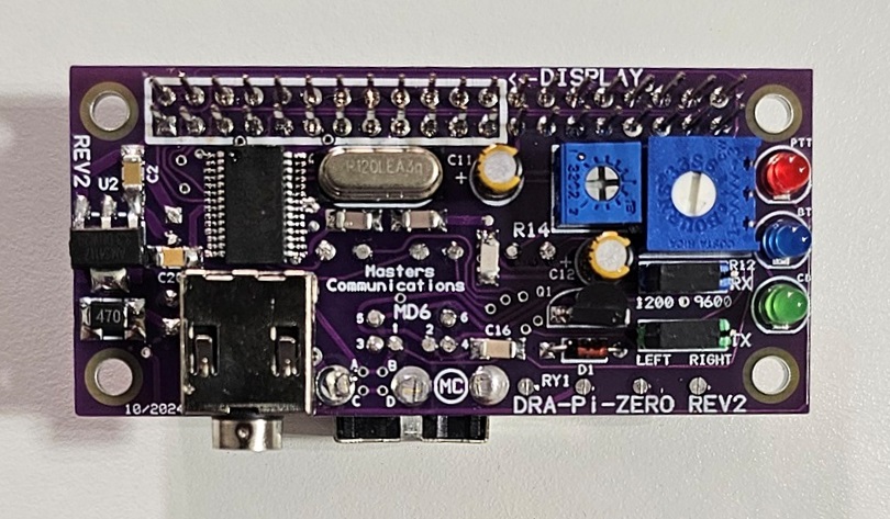
Top side photo of the DRA-Pi-Zero REV2 circuit board (click for a larger view).
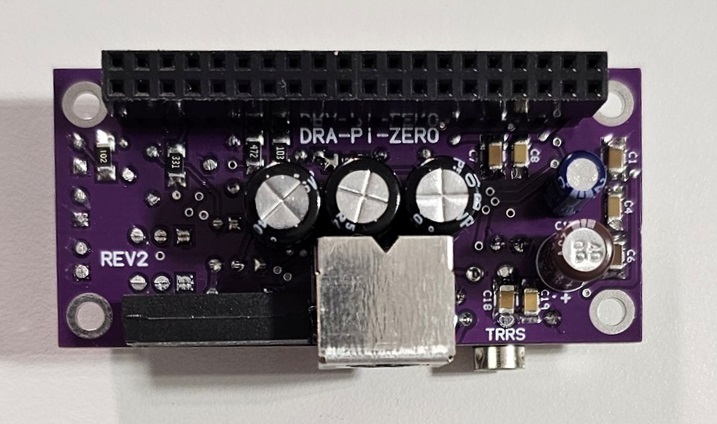
Bottom side photo of the DRA-Pi-Zero REV2 circuit board (click for a larger view).
Assembly:
Please read through these instructions at least once prior to beginning the assembly. It will
help you to understand the build process and keep you from getting stuck. Remember to look at
the photos above - they can help you with orientation and which side a component is installed on.
If you purchased our kit, refer to the parts list and make sure you have all of the components you need to build the kit. All of the components are supplied with the kit, and while we make every effort to be sure we didn't omit any components, it can happen. If you are missing anything, or ruin something, just contact us.
Click here for Parts List.
You can NOT build in vertical height order. Assembly must be done in the order provided here. If you don't follow these instructions - you may find yourself stuck and have difficulty moving forward. All parts have silkscreen part numbers, boxes or outlines to indicate which side of the board the part gets installed on. If in doubt - look at the photos. Some parts sit on the direct opposite side of the board than others, and require other components to be installed before those can be installed. Some surface mount components (SMT) are installed onto the board at a location where a plated hole (via) electrically connects one side of the board to the other. Those holes can be filled with solder.
NOTE: DO NOT fill the to large centered alignment holes of the TRRS connector with solder until instructed to install C18 near the end.
REV2 changes all resistors and some small capacitors to surface mount. All resistors on REV2 install on the bottom. REV2 notes are in [brackets].
Except for C18, get ready to install all surface mount components that are not already pre-installed. Don't install them until instructed below. This may include the voltage regulator, 7 [12] surface mount capacitors and a surface mount inductor. Some parts install on the top (the side with the 28 pin IC), while others install on the bottom. The SMT parts have been separated in small bags with their values indicated on them. If you lose reference to the SMT capacitor values - the larger ones are the 106 (10uF) - the smaller ones are the 104 (0.1uf). Unfortunately - the 22 and 47 pF caps look nearly the same and are very difficult to tell apart. The inductor has "470" on its top. All of these SMT capacitors are non polarized and can be installed either way. When soldering the voltage regulator, make sure the all pins are soldered securely - including the tab. C20 is an additional 104 capacitor on the top side of REV2 boards. Install the SMT capacitors after the resistors.
Install the inductor marked "470" on the component and L1 on the board near the voltage regulator. Now install the voltage regulator if is wasn't supplied already installed.
Install all fixed resistors on both sides of the board. All resistors on REV2 install on the bottom. REV2 boards use surface mount and their value is indicated by the value/multiplier numbering system. With REV1 boards, some resistors color bands may be hard to make out. If in doubt, use an ohm meter to verify the value before soldering it in place. The R number is inside the resistors outline (box). On REV1, install, solder and trim the leads with a good pair of flush cutters. Don't allow the remaining clipped leads to be very long.
Install C5, C9, C16, C17 and [C20] on the top side. The ground connections require a good bit of heat. Don't be afraid to keep the iron tip on these longer until the solder flows freely. On REV1 boards, trim the leads with a good pair of flush cutters. Don't allow the remaining clipped leads to be very long. On REV2 boards install the remaining SMT capacitors EXCEPT C18.
Then, install diode D1 on the top side - The square pad is the banded end of the diode.
IMPORTANT: Install the 2X20 header on the bottom side - pins up through. Make sure the header's dual spacer is flat / flush against the board when soldering. It's best to tack each corner and make adjustments as necssary - - then solder all 40 connections sparingly - but completely. Care must be exercised as to not get solder up the pins - otherwise they will need to be cleaned off so the display will go down over the pins. DO NOT cut any of the pins off before or after installation, otherwise you won't be able to install the optional display.
Install the crystal on the top side with its plastic spacer.
Next - Install the 3 LEDs on the top side observing polarity. For LEDs - the long lead goes in the round hole.
Install the potentiometers on the top side observing their size and orientation on the silkscreen.
Then - Install the two small 4.7uF electrolytic capacitors. The square pads are the + (positive) of the polarized electrolytic capacitors. These two capacitors install on the top side.
Next, install the transistor on the top (flat to flat on silkscreen).
Install the two 3-pin (TX / RX) headers on the top. The TX header is green and the RX header is blue. Then put the two jumpers on the headers in the "1200" and "LEFT" positions.
Then, install the TRRS female connector on the top side of the board. Use just enough solder to fill the holes. The ground connections require a good bit of heat. Don't be afraid to keep the iron tip on these longer until the solder flows freely.
Now, install C18 on the bottom directly under the TRRS connector. It's okay to fill the holes on each side of C18 with solder.
Next - Install the two polarized electrolytic capacitors on the bottom. I install the 10uF first, then the 100uF polarized beside it. The square holes (pads) are the + (positive) of the polarized electrolytic capacitors. The negative side of these capacitors have a stripe down the side indicating the negative connection. Make sure the capacitors are fully seated down on the board. Then, install the three larger 100uF non-polarized capacitors on the bottom. These capacitors can be installed without regard to orientation. The holes (pads) for these capacitors are both round and the capacitor can be installed either way. Make sure the capacitors are fully seated down on the board.
Now, install the Mini-DIN-6 female connector on the bottom. Completely fill the mounting holes with solder to insure mechanical stability.
Lastly, install the relay on the bottom. Orientation doesn't really matter, but you may want to install it so you can read the part number from the side.
Email
Kevin Custer for support.
TRRS Radio Cables are available from the Digirig Store. They have pre-made cables for the DRA-Pi-Zero for many radios.
Product of Masters Communications, all rights reserved.
Specifications may change without notice.
Images property of Kevin Custer - Masters Communications.
Board layout by Kevin Custer - W3KKC
HTML August 5, 2024, W3KKC All Rights Reserved!