Custom Products for the Digital Radio Amateur Enthusiast

|
Custom Products for the Digital Radio Amateur Enthusiast |
|
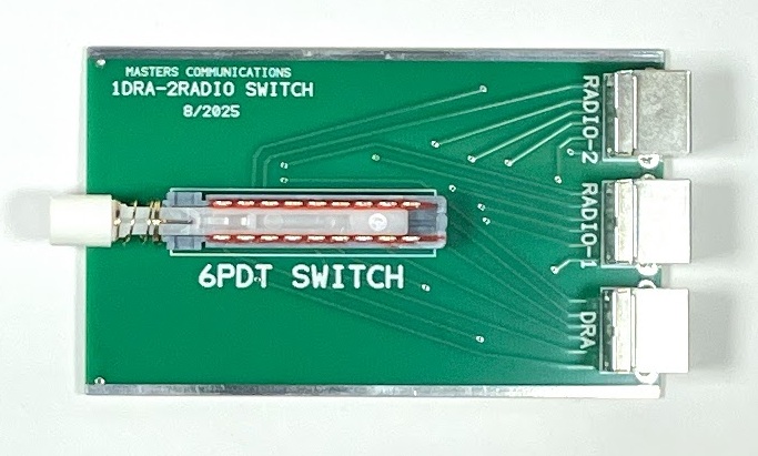
Top photo of the DRA-Switch circuit board (click for a larger view).
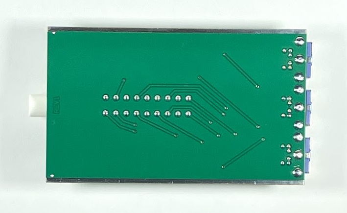
Bottom photo of the DRA-Switch circuit board (click for a larger view).
Assembly:
If you purchased our kit, refer to the parts list and make sure you have all of the components
you need to build the kit. All of the components are supplied with the kit, and while we make
every effort to be sure we didn't omit any components, it can happen. If you are missing
anything, or ruin something, just contact us.
Parts List click here.
Assembly can be done by personal choice, but you may find it easier to install the the switch, then the connectors on the end. Solder all pins and supporting holes filling them completely with solder.
Carefully align the button onto the square shaft of the switch and press it onto the shaft until it clicks into place. DO NOT force!
Finish by installing the board into the bottom slot of the metal case and then installing the front and rear panels with four screws - one at each corner.
Email
Kevin Custer for support.
Product of Masters Communications, all rights reserved.
Specifications may change without notice.
Images property of Kevin Custer - Masters Communications.
Board layout by Kevin Custer - W3KKC
HTML November 25, 2025, W3KKC All Rights Reserved!