Custom Products from Masters Communications

|
Custom Products from Masters Communications |
|
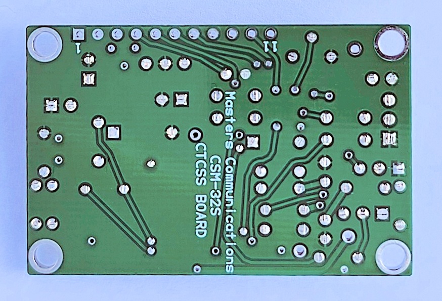
Large top and bottom photos of the CSM-32S PC board.
Click on any of them for a larger view.
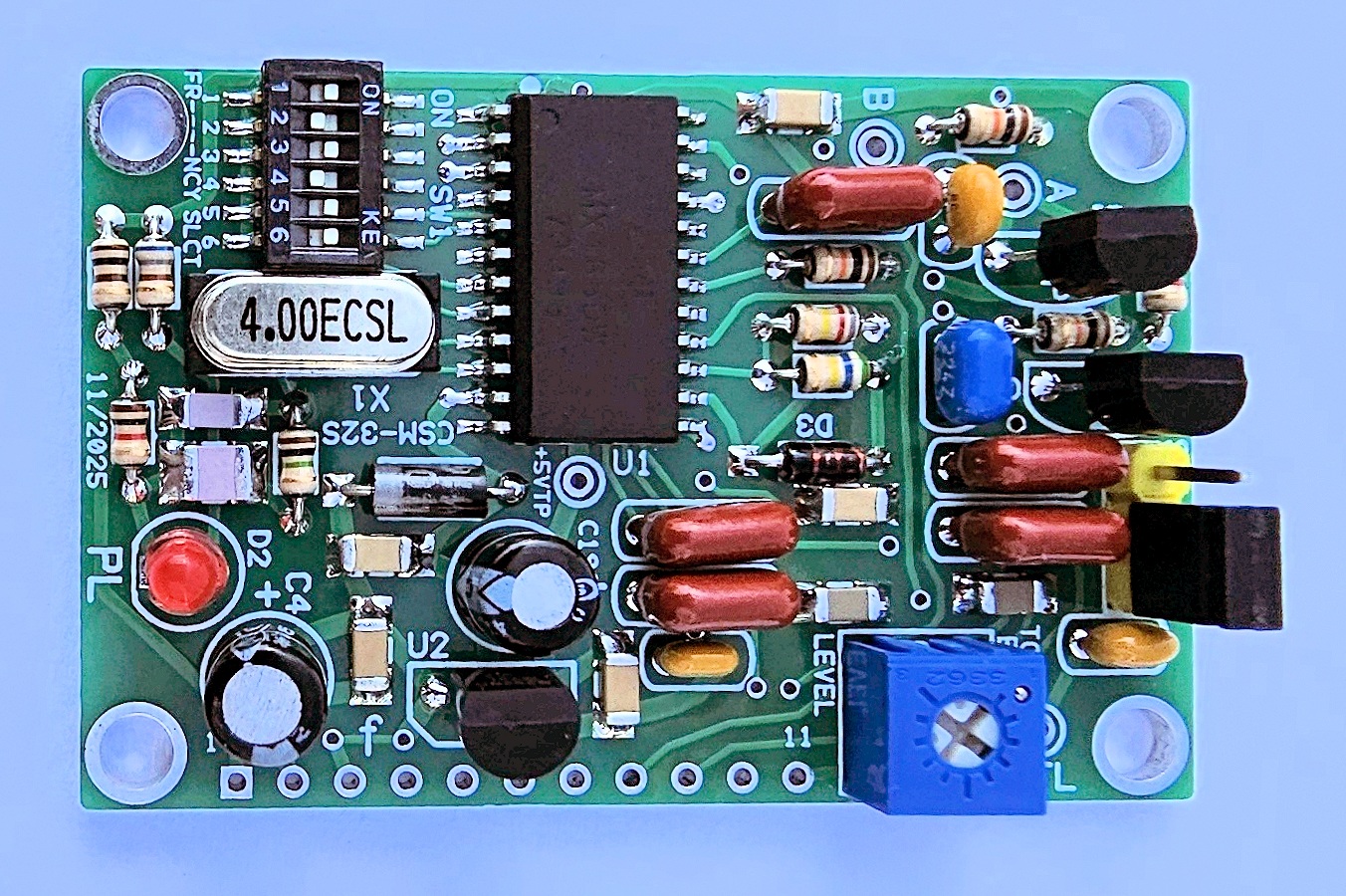
Assembly:
If you purchased our kit, refer to the parts list and make sure you have all of the components
you need to build it. Kit assembly is only recommended for experienced builders familiar with
installing small (1206) surface mount parts with a common soldering iron. Kits are supplied with
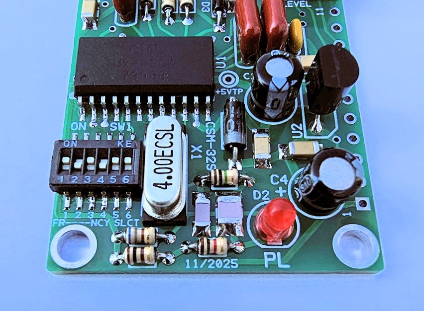
the MX465DW and 6 position DIP switch pre-installed, and cleaned of most flux residue.
NOTE - The surface mount switch has a transparent tape covering the switch openings. Leave the tape membrane in place until you install the other SMT parts and clean the board of excess flux residue. Do this when instructed below.
Parts List Click here for Parts List.
Assembly can be done by personal choice, but we recommend following the order specified below - - installing the SMT parts, then the shorter components, followed by the taller ones. The SMT parts should be installed first, following with a cleaning of the board and switch membrane removal.
NOTE - Some components may need their leads straightened prior to installation to allow the part to sit down tight against the board.
Install all surface mount capacitors. They are supplied in small bags with the part values. These are not polarized so they can be installed either way. Install one value at the time - then move onto the next value.
Now is a good time to clean the board of flux. I use denatured alcohol, but rubbing alcohol works too. Remove the protective tape from the switch after the alcohol has completely evaporated.
Install all resistors. Some resistor colors are hard to make out. If in doubt, use an ohm meter to verify the value before soldering it in place.
Install the diodes observing polarity. The square pads are the banded end of the diodes.
Install the crystal with its spacer, then the yellow and blue and brown leaded ceramic and
film capacitors.
Some capacitors are identified as follows: "124 = .12 uF, "47" = 47pF, in other words the first
two digits are the value and the third digit is the number of zeroes you add to determine the value.
Now install the LED (long lead into the round hole).
Install the electrolytic capacitors. The square pads are the + (positive) of the
electrolytic capacitors - and this is the longer lead.
Look for the (+) on the circuit board.
Install the pot.
Now install the transistors and voltage regulator - flat to flat on the silkscreen, and the yellow three pin header with its short.
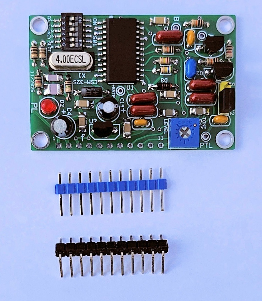
Finish by installing the straight or angle header (or not).
Information on the MX465DW.
Click here
to download a manual for the MX465DW
Email
Kevin Custer for support.
Product of Kevin Custer / Masters Communications, all rights reserved.
Specifications may change without notice.
Images property of Kevin Custer - W3KKC
Board layout by Kevin Custer - W3KKC.
HTML August 12, 2025, W3KKC All Rights Reserved!