Custom Products from Masters Communications

|
Custom Products from Masters Communications |
|
Model CH-25
Actual Size CH-25 PC board.
(Click image to enlarge)

Schematic:
(Click Here to download a PDF file of the schematic.)
Parts List: (Click Here to download a parts list text file.)
Assembly:
If you bought our kit, assembly can be done by personal choice, but you may find it easier to
install the op-amp first followed by the transistor. Solder wick is great for removing
shorts when soldering the small 8 pin IC. Alignment of the IC is not super critical, so
don't think it has to be perfect. Just make sure pin 1 (the pin closest to the line, dot
or dimple) is closest to the dot on the board. Continue with fixed resistors and capacitors,
making sure not to mix up the values. The yellow or blue capacitors with the close lead
spacing are the 1uF. Finish up by installing the pot, voltage regulator, and header pins
last. Orientation of the header pins is personal preference. I position them so the
latch of both connectors sits to the inside of the circuit board. You'll need to assemble
the header sockets with lengths of wire to reach power, and the support components for the
crystal. These leads should be kept as short as possible. The leads shouldn't be
more than 12 inches long, for optimum stability of the sensor.
Installation:
This device is intended to heat the crystal and surrounding components, so other components in
the element/ICOM are not exposed to a great temperature change. Existing 'compensation
components' aren't changing against ambient temperature changes. This should preclude you
from having to change anything else except possibly the fixed ranging capacitor - so the netting
capacitor (trimmer) can be centered. You need to properly insulate the oscillator and
surrounding components for best results. Any type of cover will need to be removed from
the element/ICOM for placement of the heater resistor(s) and sensor. This may take up room that
won't allow for the cover's re-installation. Wires connecting to the heater and sensor can
pose a concern as to their routing. Be sure not to pinch them or short out any wiring or
other components with the re-installation of any cover, especially metal types. The board
can be mounted with double stick foam tape or stand-offs (not included). Caution, the
mounting holes are at ground potential, so choose your mounting location appropriately!
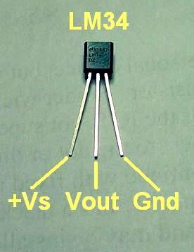
Here is a photo of the LM34 temperature sensor and its pinout for your convenience.
Installation of the heater resistors and temperature sensor can be done in a way to allow the original metal or plastic cover to be reinstalled onto your TCXO, channel element, or ICOM. You can solder the ground end of the resistors directly to the crystal case for added heat transfer. I use epoxy (not included) to complete the attachment of the heater resistors and LM34 sensor to the crystal case. Be careful if using compounds which are conductive, as they could short out the circuit or sensor. You may have to rearrange the components inside the crystal holder to make room for the heater resistors and sensor. In a standard GE MASTR II ICOM the .01 uF poly capacitor under the crystal can be changed out to a surface mount device. This gives plenty of space for the crystal and added heater and sensor components to fit and allow the metal cover to go back on. You can cut a slot in the cover to allow the 5 wires to be routed outside the element to the printed circuit board.
Real-World Installations:
Modification of the GE ICOM to deal with the CH25. Click
Here for a photo article.
The CH25 doesn't have to be used to heat a crystal. One enterprising user is heating a flaky DSP chip inside his expensive A/V receiver to get one of the inputs to work properly. Click Here for a photo article.
Photo of heater resistors and temperature sensor ready to be epoxied to a HC6/U crystal.
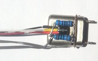
Make sure when you make the 5 conductor "cable" between the board and the device being heated
that you don't skimp on the second ground wire. The separate ground is necessary to insure
stable and accurate operation.
Setting the temperature:
Once built, installed, and operating properly, the temperature of the crystal can be set by
measuring the voltage on the Vout pin. The temperature on this pin follows a 10mV output
per °F., so 140°F is 1.400 Volts DC - etc. If you bought crystals for a particular
inflection point, set the temperature to match it. 140°F is 60°C. 140°F
is also a good temperature for a crystal that was not necessarily designed to operate at an
elevated temperature. If you have standard crystals that were made for a nominal 25°C
unheated operation, you may find a point between 120°F and 140°F at which the crystal
becomes more stable. Feel free to operate the crystal at whatever temperature produces the
best stability, as long as that temperature will always remain above any ambient influences
as the radio gets hot.
Secure PayPal ordering available from products main index page.
Email
Kevin Custer for ordering information, order by check, and/or quantity pricing of this exciting product.
Product of Kevin Custer - W3KKC, all rights reserved.
Specifications may change without notice.
Original concept
and circuit design by Bob Dengler - NO6B
Images property of Kevin Custer and Chuck Kelsey - WB2EDV
Board layout by Chuck Kelsey.
Photo of LM34 by Robert Meister - WA1MIK
HTML April 15, 2014, W3KKC All Rights Reserved!