Custom Products from Masters Communications

|
Custom Products from Masters Communications |
|
Model FL-10
Actual Size FL-10 PC board.
(Click image to enlarge)

Schematic Image.
(Click image to download a PDF copy)
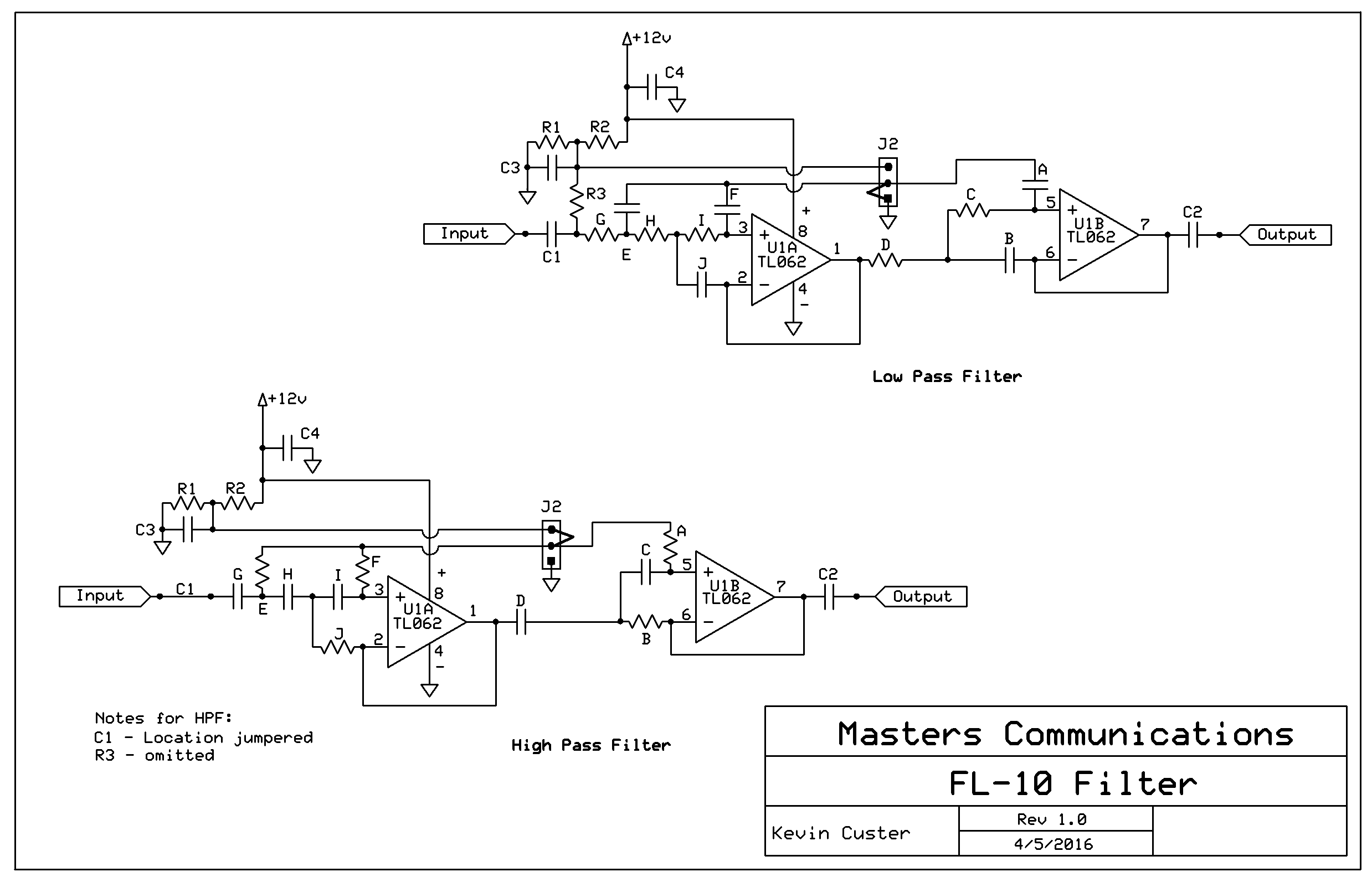
Overview:
The FL-10 is a 5 pole active filter using two op-amp sections. The circuit board was
designed to allow the filter to be configured either low-pass (LP) or high-pass (HP).
Switching between the two is done by the existence of R3, the position of jumper J2, and
by the selection of the components which have a letter
designation. "Lettered" components can be resistors or capacitors (or absent) depending
on the desired configuration.
Please note you cannot change the configuration of the filter from LP to HP (and vice versa) with a mere change of J2's position. As such, this wire jumper is soldered into the appropriate location when the board is populated, and no header is provided.
Components A - E - F get tied to ground through J2 when configured for LP operation.
Conversely, components A - E - F get tied to 1/2Vcc (bias) through J2 when configured for HP
operation.
When used with the RA-35/40/42/DR1X, and DRA-45/50/65, and 70, the FL-10 configuration is LP, with the knee at approximately 4 kHz, or 15 kHz depending on your needs. Good engineering practice tells us it's desirable to LPF the output of the CM119A when driving a naked FM modulator not having any protection from high frequency energy; preventing spurious emissions. 15 kHz was chosen so the RA-35/40/42/DR1X, and DRA-45 works with most digital deployments, but still protects against spurious emissions beyond the filter's cut-off. When the RA or DRA is intended for use in analog voice or 1200 baud digital data systems, a knee of 4 kHz is recommended to insure adjacent channel splatter doesn't occur. For wide-band voice or high-speed data, a filter knee of 15 kHz is recommended.
The use of this filter is optional in the RA and DRA Series radio adapters. Some people will be feeding a MIC input that is protected from generating spurious emissions by default of the existing limiter/filter. In those instances, this filter is not needed or recommended.
When used as a CTCSS reject filter, the FL-10 is configured HP, and the knee is set at 350 Hz. The supplied op-amp is a high-performance TL062, and when run from 10V or more has excellent dynamic range and low noise. Of course, the IC is socketed in case the builder chooses to use some other op-amp they consider superior.
These filters were optimized by Robert Meister WA1MIK. Bob reworked the part values
for the best performance. The CTCSS filter was designed to give a good compromise between
maximum rejection of CTCSS tones below 186.2 Hz and minimizing the voice roll-off below 400
Hz. Many thanks go to Bob for his time and effort to help bring you these quality
filters. Be sure to check out his evaluation article.
FL10 Evaluation
Assembly:
If you purchased our kit, refer to the parts list and make sure you have all of the components
you need to build it.
Click here
for Parts List.
Assembly can be done by personal choice, but you may find it easier to
install the resistors first, followed by the capacitors, jumper(s), IC socket, and header socket.
The resistor color bands can be difficult to see without good lighting and strong magnification. If in doubt, use an ohmmeter and double check the value before soldering resistor components in place. Please refer to the additional notes about component identification in the parts list.
Installation:
This device is intended to be installed inside a radio or project box for protection. When
used with the RA-35/40/42/DR1X, and DRA-45, the mating 4 pin in-line socket allows the FL-10 to
simply be plugged onto the radio adapter by first removing the shorting jumper on the audio header.
Refer to the notes in the low-pass section of the parts list for additional installation
instructions when this filter is used with the RA and DRA Series radio adapters.
Refer to the board silkscreen when this filter is used with equipment other than the RA and DRA Series.
GND = ground
O = output
I = input
+V = supply voltage
Email
Kevin Custer for ordering information.
Product of Kevin Custer - Masters Communications, all rights reserved.
Performance optimization of these filters by Robert Meister - WA1MIK.
Specifications may change without notice.
Images property of Kevin Custer - W3KKC