Custom Products for the Digital Radio Amateur Enthusiast

|
Custom Products for the Digital Radio Amateur Enthusiast |
|
Product Support Documentation
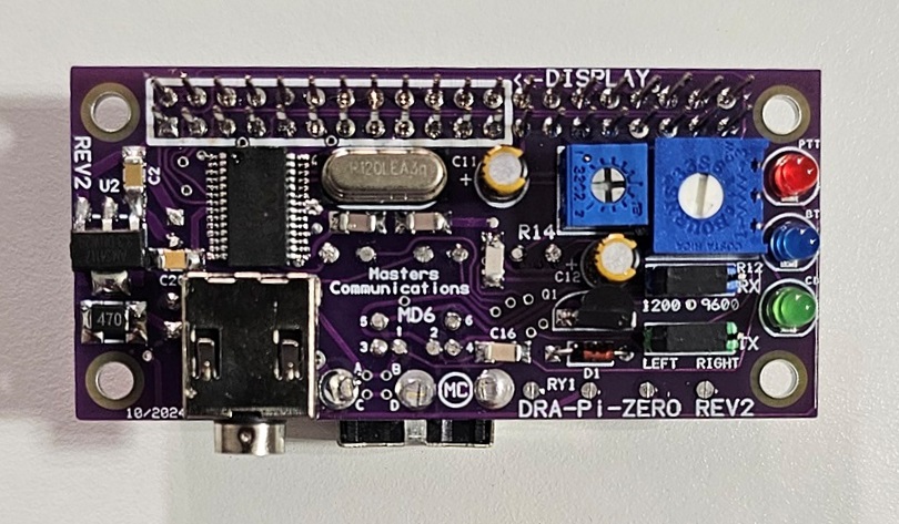
Model DRA-Pi-Zero REV2
Top side of DRA-Pi-Zero - shown considerably enlarged.
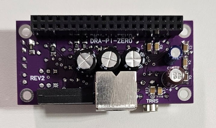
Bottom side of DRA-Pi-Zero - shown considerably enlarged.
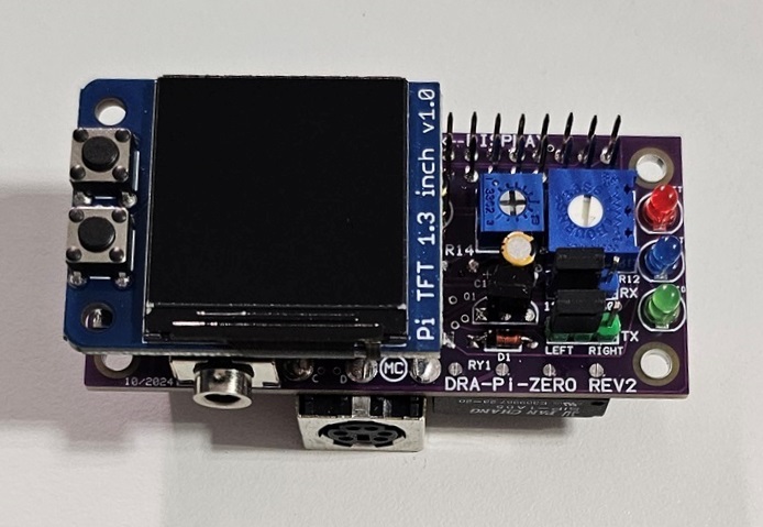
DRA-Pi-Zero with optional display - shown considerably enlarged.
Schematic Image of REV1 - Click to download a high quality PDF.
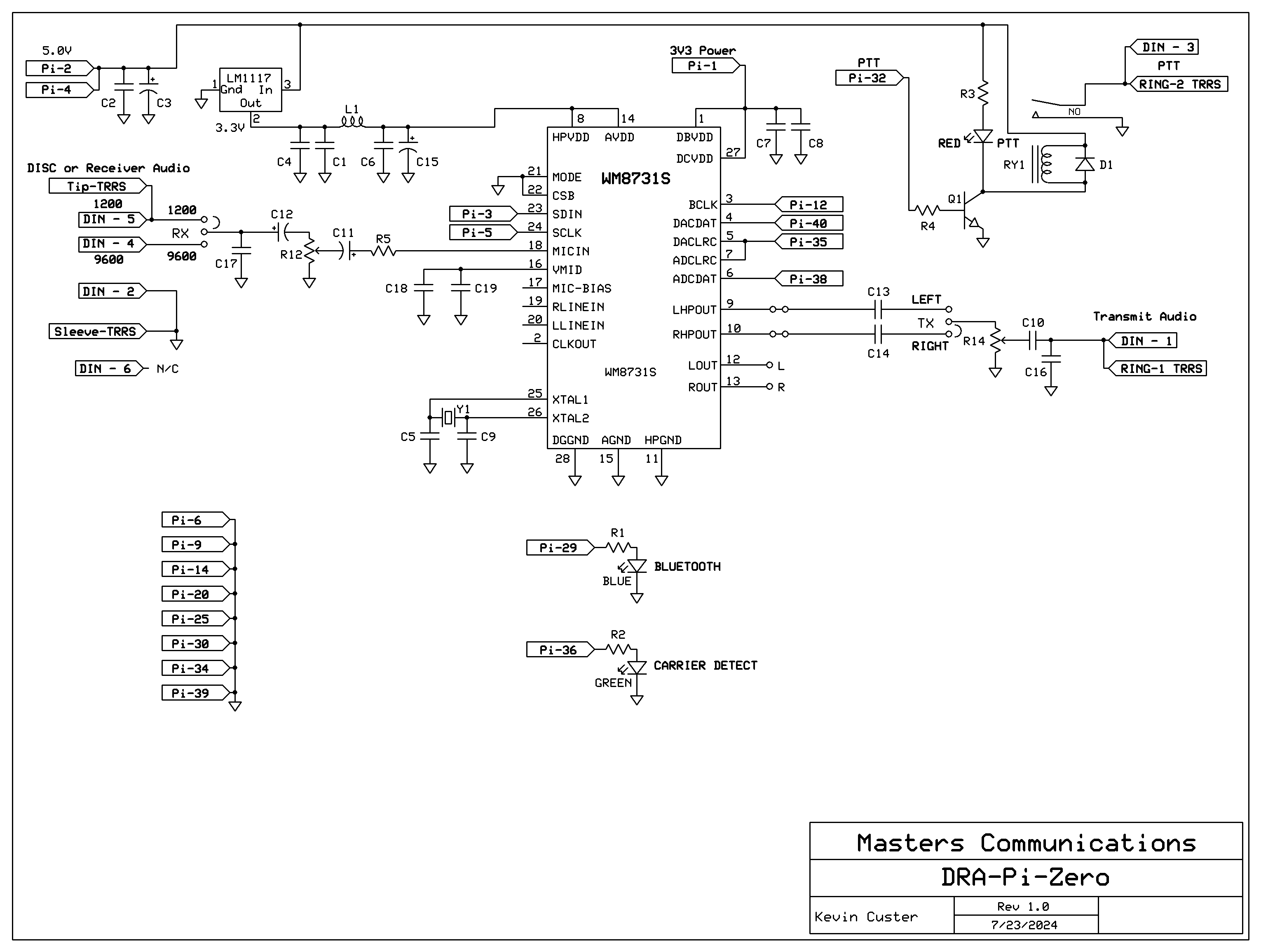
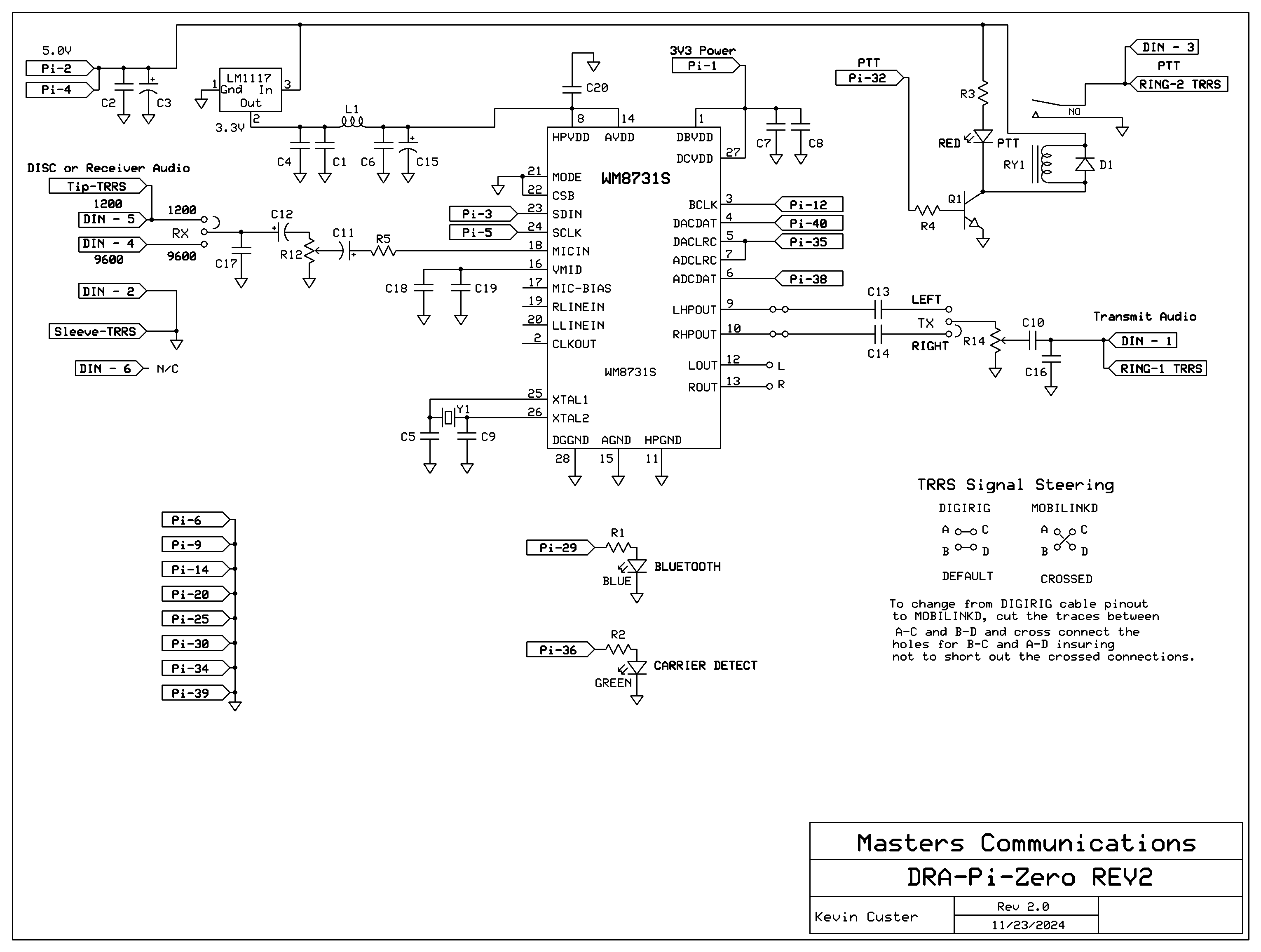
Schematic Image of REV2 - Click to download a high quality PDF.
Overview of DRA-Pi-Zero
Things that may not be otherwise obvious:
Parts List:
If you purchased our kit, refer to the parts list and make sure you have all of the components
you need to build it.
Click here
for Parts List.
Construction/Assembly:
Click here for assembly instructions and construction notes - with large photo.
Jumper Settings:
Click here
for Header / Jumper settings and other board connection assignments.
Mini-DIN-6 Pinout:
Click here for MD6 pinout in text.
Click here
for an image of the Mini-DIN-6 data jack.
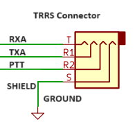
3.5MM TRRS Pinout:
Click here
for TRRS Pinout.
Installation:
This device is intended to be installed onto a Raspberry Pi Zero 2W (NOT included) - but will
work on any Raspbery Pi with a compatible 2X20 pin header and acceptable power supply. If your
Raspberry Pi has an optional heatsink on the prcessor - it will need to be carefully removed to
provide the necessary clearance for the DRA-Pi-Zero to fully seat on the 2X20 header. A thermal
pad of the proper thickness (not supplied or included) can be installed optionally to allow
the Mini-DIN-6 radio connector to be used as a heatsink with some Raspberry Pi's.
Compatibility:
The DRA-Pi-Zero has been tested with DigiPi VER 1.9-1 software on a Raspberry Pi5, 4, 3, and
Zero 2W, and works as intended.
Configuration:
Please refer to the instructions on the DigiPi website
for configuration settings using this device.
See Craig's unboxing video.
Refer to the schematic for the pinout of the MD6 and TRRS where all of the logic signals, power
connections, and audio signals are listed.
Custom TRRS radio cables are available from the Digirig Store. They have several pre-made cables that work with the DRA-Pi-Zero for many radios. Mobilinkd cables are not compatible as the PTT and TX audio are reversed. REV2 boards allow for reconfiguration to use Mobilinkd cables but the process is VERY difficult because of the size of the board and what's required to make the change. Contact Kevin if you want further details, but he recommends using Digirig cables.
Recommended powering requirements:
Raspberry Pi's don't like to be under powered. We recommend a high-current capable power supply for
the system. Something capable of 2 amps or more is best. Separate 3.3V powering is provided for
the digital and analog sections. The board is supplied with 5 VDC from the 40 pin connection from
the Raspberry Pi. Onboard linear regulation is provided for the higher current analog 3.3V
loads (CODEC Analog) insuring low-noise and high signal to noise ratio.
Recommended receive audio input level:
The DRA-Pi-Zero accepts the widest range of audio compared to any other similar radio adapter interface.
The input signal is attenuated by potentiometer R12, giving the broadest range of acceptable levels.
If your receive audio level is adjustable or programmable (at the radio),
we recommend around 2.0 volts P-P. This allows very good signal-to-noise
ratio and low cabling cross talk. This level results in a 50% rotational setting of the
potentiometer. Additional audio level setting is available from AlsaMixer - advanced Raspberry Pi
operational understanding is required.
Transmit audio output capability:
The transmit audio output level is adjusted by the smaller pot (R14). The LEFT / RIGHT "TX" header
selects which channel feeds the transmitter - no soldering is required to make the selection. The
TX audio signal is fed from the high-power headphone outputs to the TX header. Maximum TX output level
is 3.0V P-P with a 500 ohm load and 2.8V P-P with a 30 ohm load - TX pot wide open and Alsamixer set
to "Max White" (no red). Most portable radios don't need additional AlsaMixer adjustment - the default
setting of 37 is usually good for HT's. But - some radios require elevated transmit audio (many radios
like Yaesu and Kenwood mobiles. These radios might require a master level setting in the 70's -
especially when driving the modulator directly.
PTT Keying:
The DRA-Pi-Zero uses a relay for PTT switching. Some radios don't like a transistor, and the use of
a relay eliminates any keying issues due to the junction loss of a transistor. FET's and other transistor
switching is fast - but the reed relay we use is almost as fast. For the protocols this hardware
supports - it's plenty fast enough. The 2N7000 is a popular PTT transistor but will lock up in
the presence of RF (RFI). The last thing we want is for the radio interface to lock PTT "on" solid -
and require a hard reboot to resolve it.
More below.
Red "PTT" LED:
The Red LED indicates the successful assertion of
Push To Talk (PTT). This LED is in parallel with the coil of the relay.
PTT logic is driven from pin 32 of the 40 pin Raspberry Pi 2X20 header.
Pin 32 is labeled "GPIO 12" on the
official Raspberry
Pi header description page. There is no provision to use a separate / different
Raspberry Pi GPIO (pin / function) to illuminate the Red LED or actuate the PTT relay.
Online ordering available from the DRA-Pi-Zero main page.
Email Kevin
Custer for support of this
exciting product.
Product of Masters Communications, all rights reserved.
Specifications may change without notice.
Images property of Kevin Custer - W3KKC
Board layout by Kevin Custer - W3KKC.
HTML August 4, 2024, W3KKC All Rights Reserved!