Custom Products from Masters Communications

|
Custom Products from Masters Communications |
|
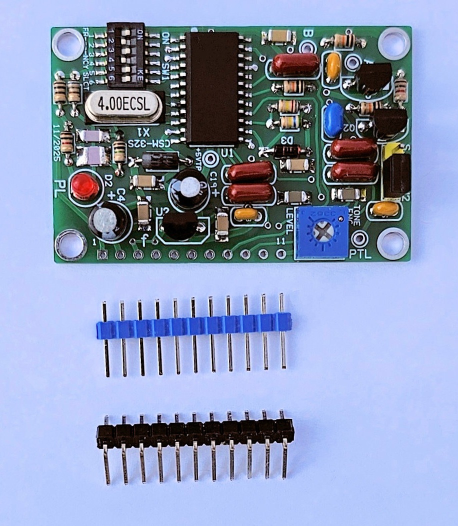
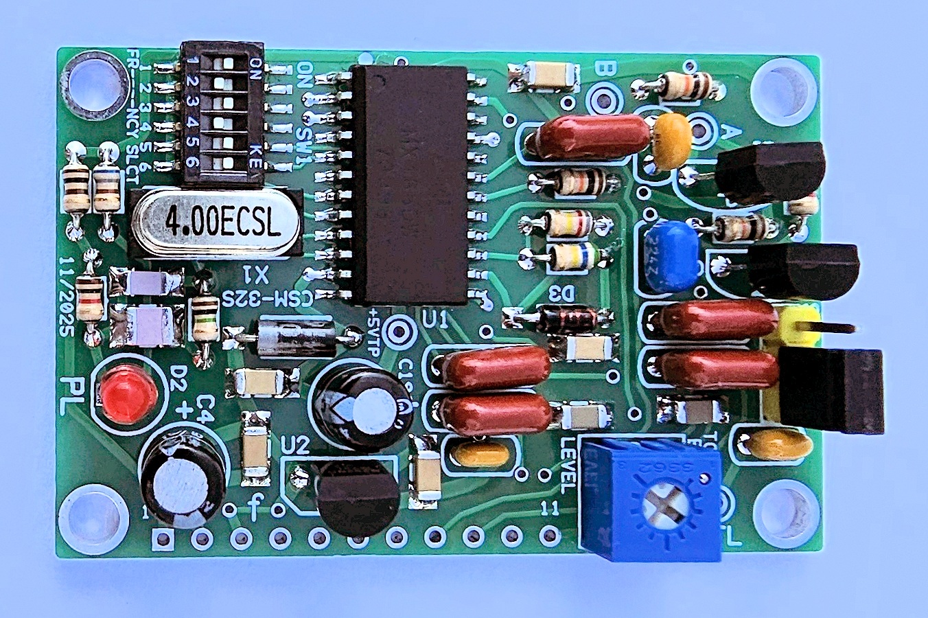
Model CSM-32S
Actual Size CSM-32S PC board.
(Click any image to enlarge)
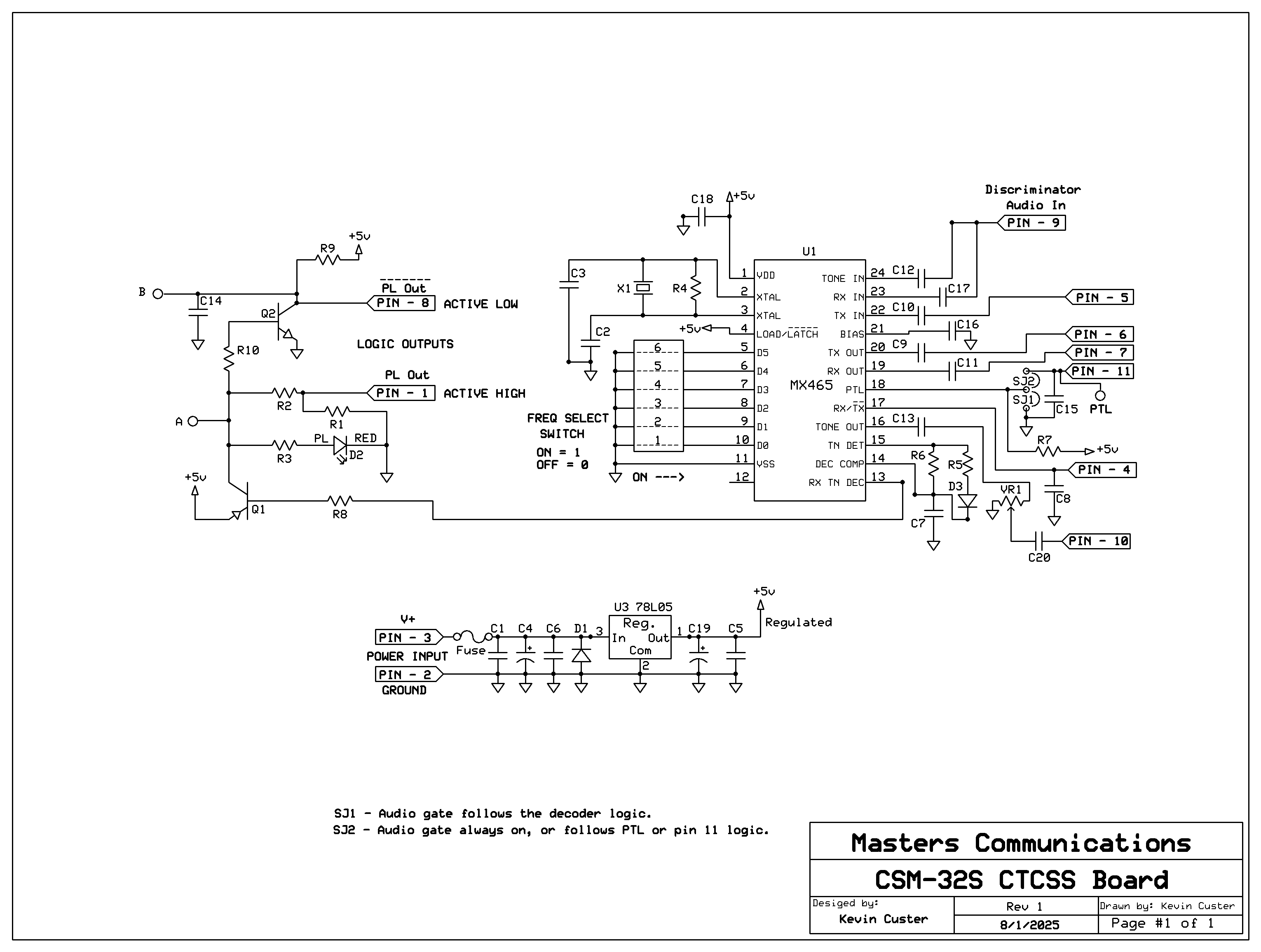
Schematic Image - Click to download a PDF file.
Overview:
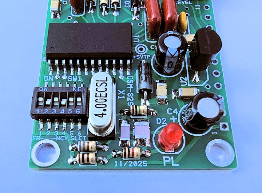
The CSM-32S is a CSM-32 with an added 6-position frequency selection switch. There are no other
differences between the earlier version and this updated one with a DIP switch. This board will provide
quality logic signals for driving a repeater controller or other radio
interface device. It requires a few hundred mV RMS of discriminator audio and a source of DC power.
It can generate a CTCSS tone and its output is controlled by a pot.
The kit is only recommended for experienced builders. If you purchased our kit, refer to the parts
list and make sure you have all of the components you need to build the kit. While the
24 pin chip is pre-installed, other moderately small (1206) surface mount parts do exist.
Parts List Click Here for Parts List.
Construction / Assembly:
Construction Article for assembly
with construction notes and large photos.
Installation:
This device is intended to be installed inside a radio or project box for protection.
Refer to the schematic and link below for the pinout of the 11 pin header where all of the logic
signals, power connections, and discriminator audio input, and filter outputs are listed. The
four holes can be used for mounting on stand-offs and these holes are at ground potential.
11 Pin Connector
Click Here for the 11 pin header and other board connection assignments.
Setting the CTCSS tone frequency:
Tone Frequency
Click Here for switch settings.
1 = ON
0 = OFF
In the photos at the top of the page, the CSM-32S is set to 123.0 Hz.
Recommended powering requirements:
The board requires a recommended minimum of 7 VDC to put the regulator into full
regulation. The maximum recommended voltage is 16 VDC, however, the
voltage regulator will survive up to 24 VDC before damage occurs.
Recommended discriminator audio input level:
For best CTCSS detection and dynamic range,
an input of at least a few hundred mV RMS of raw discriminator audio (noise) at the input of the board
is required. This equates to about .85V peak to peak of noise
at a minimum. 750mV RMS (about 2.1V peak to peak of noise), is about the maximum amount of audio
that should reach the input of the board. Again - this is noise, the actual level of the tone will
be much lower in amplititude with a full quieting signal as compared to the noise of a no
quieting signal. If you have too much audio, the
decoder may false a lot, and
a simple resistor divider in series with the input will reduce the input to a more
desirable level. Input level is somewhat dependent on the type of receiver,
characteristics of the discriminator. If you have too little audio, reliable decoding
might not be possible and
a simple audio amplifier may be required to meet the required input level of the board.
Refer to
this amplifier project (the first one) if necessary.
Explanation of the logic signals and other pins:
Both active high and active low logic outputs are available on the 11 pin header.
In addition, optional open collector outputs are available from 2 holes on the circuit board.
These optional outputs can be used for operations that are beyond the original scope
of this board.
A pull-down resistor is included on the logic high output. Obviously if you are using this board and need an active low output you should be using the output connected to the NPN transistor, but, the on-board pull-down resistor can make circuitry respond correctly when using the active high PNP output. Likewise, a pull-up resistor is included on the logic low output for the same reasons.
All logic is sourced from +5V and ground. +5 volts is the logic value expected directly from the collector of a PNP logic transistor that is biased on. Ground is the logic value expected directly from the collector of a NPN transistor that is biased on.
The normal logic outputs that connect to the header should satisfy most of the equipment you'll connect to this board. For those instances where they don't, you can use the optional outputs labeled A - B. These outputs are available from "holes" on the circuit board, marked A - B on the silkscreen. These outputs connect directly to the collectors of the logic transistors before any current limiting resistors. Caution should be given to the use of any of these additional outputs as they are unprotected, and misuse will cause switching transistor failure. While the PNP transistor has the over-current protection of the 5 volt regulator, there is no protection for the NPN to ground. Be certain that your connection to these outputs don't exceed the capabilities of the board or switching transistor.
The SJ1/SJ2 header allows the PTL function to be selected remotely. Normally, this jumper will be in the SJ2 position - which enables audio on the RX Out continuously, as long as PTL or pin 11 is not grounded. Selecting SJ1 gates the filtered audio when the decoder is not decoding a tone, and passes audio when the red LED is lit. Refer to the manual download below to see what this function is, what it does, and how to use it.
The encode output is capacitively coupled and the output impedance is 10k ohms. The board will provide a little more than 2.0V P-P of encode audio with the pot at maximum (CW) rotation.
Information on the MX465DW.
Click here
to download a manual for the MX465DW
Email
Kevin Custer for support of this exciting product.
Product of Masters Communications, all rights reserved.
Specifications may change without notice.
Images property of Kevin Custer - W3KKC
Board layout by Kevin Custer - W3KKC
HTML August 12, 2025, W3KKC All Rights Reserved!