Custom Products for the Analog & Digital Radio Amateur Enthusiast

|
Custom Products for the Analog & Digital Radio Amateur Enthusiast |
|
Analog Measurement Unit (AMU)
For Analog & Digital Two-Way Radio
Applications
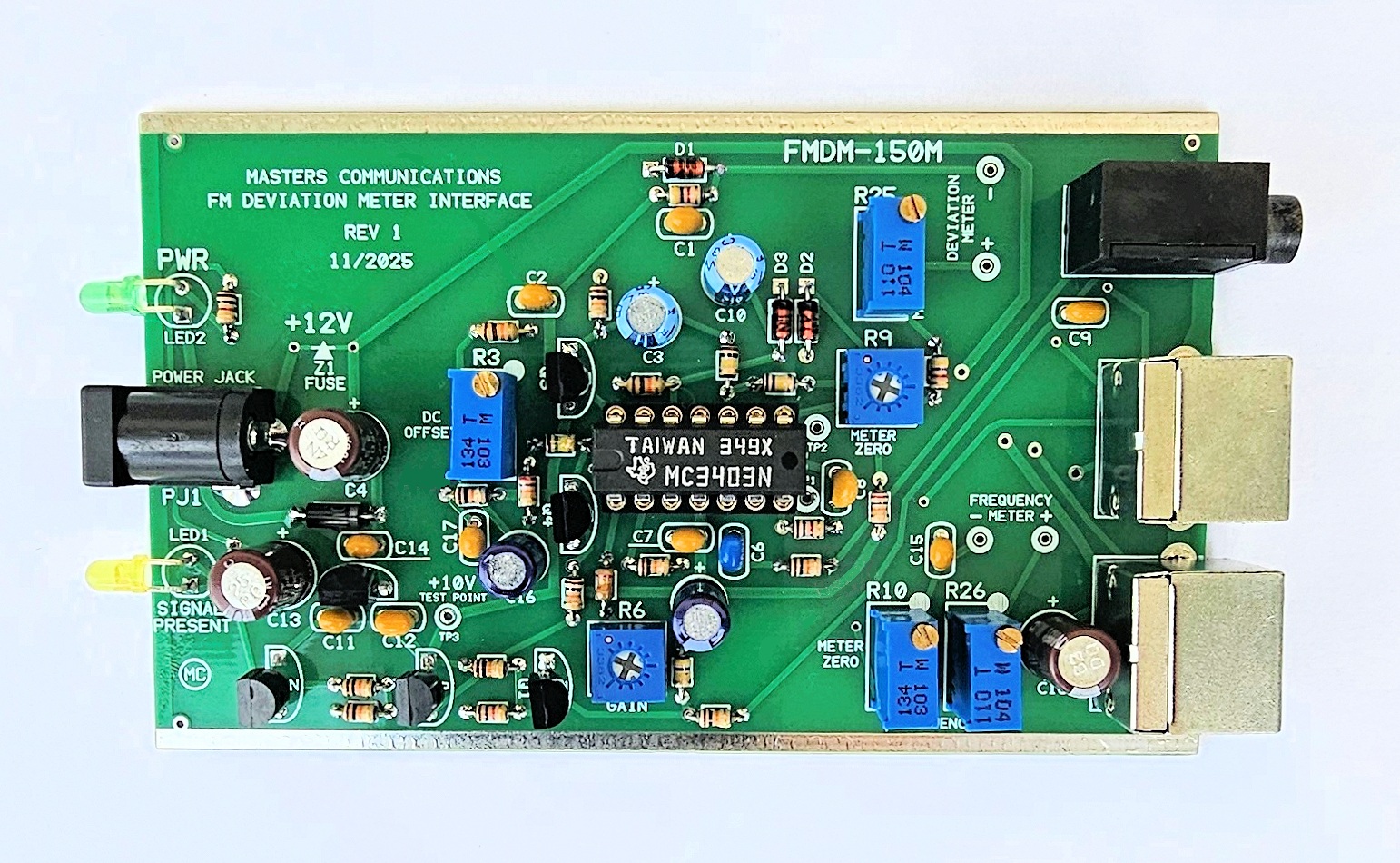
Top side of FMDM-150M Analog Measurement Unit (AMU) circuit board - shown slightly enlarged.
(Click photo to show a larger image)
Schematic Image - Click to download a high quality PDF.
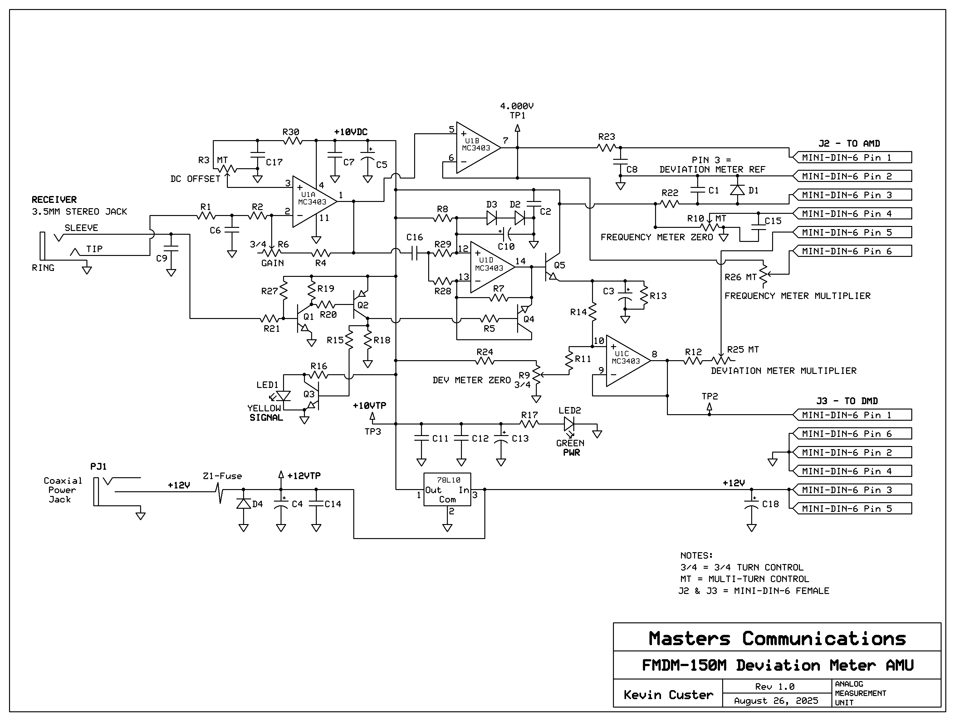
The scanner is modified to additionally bring the squelch status logic to the AMU and used to mute the AC coupled deviation measurement signal path. The DC path is not squelched so the frequency error meter and oscilloscope oututs are active all the time. The second is the frequency error meter - with more detail on it provided below under the analog meter panel section. The third is the use of multiturn pots for greater operating stability and easier calibration.
The original circuitry was driven by a legacy Radio Shack PRO-2012 scanner that uses a different I-F / demodulator that chip (TK10420) which has a different output level and biasing point as compared to the Uniden Bearcat BC355N. The latter uses a NJM2552 demodulator chip. That requires the AMU to be calibrated using a different method, and results in an oscilloscope output that is 100mV per kHz of deviation instead of 150mV/kHz that's stated in the original article . This doesn't change the accuracy, it just changes the way the unit is calibrated - insuring measurement accuracy. The AMU's component values are chosen to work with the Bearcat BC355N. This also means the AMU (as supplied) will not work with a Radio Shack PRO-2021 scanner. With 100mV / kHz of deviation, the math is simple for reading deviation directly with an oscilloscope. 500mV P-P equals 5kHz deviation.
The circuit board for the analog measurement unit has all of the adjustments on it to provide proper calibration. The front panel has a coaxial DC connection for the supply of power, and two LEDs to indicate power and squelch status. The rear panel has two Mini-DIN-6 female connectors to route signals to the meter displays, and a 3.5mm stereo jack to input discriminator audio and squelch logic from the scanner / receiver.
Parts List:
If you purchased our kit, refer to the parts list and make sure you have all of the components
you need to build it.
Click here
for Parts List.
Construction/Assembly:
Click here for assembly instructions and construction notes - with large photo.
Installation:
This device is intended to be installed beside the scanner and connected with short male
to male stereo cable and (2) male to male Mini-DIN-6 cables to the display(s).
Calibration:
A complete calibration procedure is available from
the Calibration Article.
Secure PayPal ordering is available on the FMDM-150M main page.
Email
Kevin Custer for support, ordering information, order by check, or support of this
exciting product.
Product of Masters Communications, all rights reserved.
Specifications may change without notice.
Images property of Kevin Custer - W3KKC
Board layout by Kevin Custer - W3KKC.
HTML December 7, 2025, W3KKC All Rights Reserved!